Table of Contents
Advertisement
Quick Links
SigmaAldrich.com
®
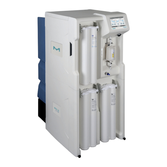
User Manual Milli-Q
CLX 7000 Series
Merck, Milli-Q, and Sigma-Aldrich are trademarks of Merck KGaA, Darmstadt, Germany or its affiliates. All
other trademarks are the property of their respective owners. Detailed information on trademarks is available
via publicly accessible resources.
© 2021 Merck KGaA, Darmstadt, Germany and/or its affiliates. All Rights Reserved.
The life science business of Merck operates
as MilliporeSigma in the U.S. and Canada.
Advertisement
Table of Contents

Subscribe to Our Youtube Channel
Related Manuals for Merck Milli-Q CLX 7000 Series


Summary of Contents for Merck Milli-Q CLX 7000 Series
- Page 1 User Manual Milli-Q CLX 7000 Series Merck, Milli-Q, and Sigma-Aldrich are trademarks of Merck KGaA, Darmstadt, Germany or its affiliates. All other trademarks are the property of their respective owners. Detailed information on trademarks is available via publicly accessible resources.
-
Page 2: Table Of Contents
Contents Legal Information..............3 Safety Information..............4 Recycling................5 Preface.................. 6 Specifications................ 7 Feed Water Specifications................8 Electrical Specifications................9 System Dimensions...................10 Weight Specifications................11 Environmental Specifications..............12 System Overview..................13 Using the System..............14 Operating Principle..................15 System Display..................16 Overview Screen..................17 Ready..................... -
Page 3: Legal Information
Trademarks Elix, Progard, Q-Gard, Opticap and A10 are registred trademarks of Merck KGaA, Darmstadt, Germany. The " M " logo is registered trademark of Merck KGaA, Darmstadt, Germany. All other trademarks are trademarks of their respective manufacturers. Document Reference: USER-LRG2-CLX-EN... -
Page 4: Safety Information
User Manual | Safety Information | 4/53 Safety Information Symbol What it means This UV RADIATION sticker is used to refer to a position on the system cabinet or inside of it where exposure to UV light is possible. This HAZARD sticker is used to refer to a position on the system cabinet or inside of it that could be hazardous. -
Page 5: Recycling
User Manual | Recycling | 5/53 Recycling Directive 2012/19/EC: For European users only. The symbol "crossed bin" on a product or its packaging indicates that the product should not be treated like household waste when discarded. Instead, the product should be disposed of at a location that handles discarded electric or electronic equipment. -
Page 6: Preface
User Manual | Preface | 6/53 Preface Thank you for purchasing our water purification system. For correct operation, read and fully understand the contents of this user manual before attempting to use the system. It is recommended to store this user manual in a safe and convenient place where it can be easily referred to when required. -
Page 7: Specifications
User Manual | Specifications | 7/53 Specifications... -
Page 8: Feed Water Specifications
User Manual | Specifications | 8/53 Feed Water Specifications The system has been designed to operate within feed water specifications: Parameter Value or range Pressure 2 – 6 bar Flow rate > 10 L/min @ 2 bar Feed water type Potable water Temperature 5 –... -
Page 9: Electrical Specifications
User Manual | Specifications | 9/53 Electrical Specifications The systems can be supplied by Mains electricity 90-253 VAC with a frequency range from 48 to 62Hz. Table 1: Electrical specifications System type Voltage Power Consumption (VA) Milli-Q CLX 7040 and 7080 220-240 VAC @50/60 Hz ®... -
Page 10: System Dimensions
User Manual | Specifications | 10/53 System Dimensions Milli-Q CLX 7000 Seriesdimensions: ®... -
Page 11: Weight Specifications
User Manual | Specifications | 11/53 Weight Specifications The location where the system is installed needs to fully support its operating weight: System type Dry weight Kg Shipping weight Operating weight (Lb) Kg (Lb) Kg (Lb) Milli-Q CLX 7040 106 (233.7) 134 (295.4) 216 (476.2) ®... -
Page 12: Environmental Specifications
User Manual | Specifications | 12/53 Environmental Specifications Environmental specifications have been defined for normal system operation. Altitude ≤ 2000 m Ambient operating temperature 10 – 40 °C Relative humidity 80% up to 31°C (decreasing linearly to 50 % relative humidity at 40 °C) Ambient storage temperature 0 –... -
Page 13: System Overview
User Manual | Specifications | 13/53 System Overview System, components and connections are shown in the illustration below. 1. Display 16. Tank waste 2. System name 17. Power entry (Mains) & switch 3. USB port 18. Data output port 4. Matrix code (containing system serial number and 19. -
Page 14: Using The System
User Manual | Using the System | 14/53 Using the System... -
Page 15: Operating Principle
User Manual | Using the System | 15/53 Operating Principle A water system is intended to purify mains water and to automatically supply purified water to a clinical analyser. • The water system purifies tap water using a Progard Pack(s) and Reverse Osmosis ®... -
Page 16: System Display
User Manual | Using the System | 16/53 System Display Tapping display button icons moves the display between screens and launches applications. The Overview screen is the main screen and navigation to and from the Workspace screens containing the system applications is done using the display icon buttons on the bottom right of the screens. -
Page 17: Overview Screen
User Manual | Using the System | 17/53 Tapping on the screen when the screensaver is active will wake the system and open the Overview screen. Overview Screen The Overview screen is the default view on the system display. It is divided into 3 sections and each section represents one of the 3 parts of the water system. - Page 18 User Manual | Using the System | 18/53 1 Bar graph showing water quality in MΩ.cm @ 25°C and the alarm setpoint (black triangle). 2 Displays Makeup water quality in a user defined unit. TC is displayed when Temperature Compensation (TC) mode is If the water quality measured is under the setpoint, this value blinks between blue and red.
- Page 19 User Manual | Using the System | 19/53 Capacity remaining (%) Consumable due for replacement (Blinking) D1: Progard ® status and gauge (Depending on system type, one or two Progard ® be displayed) D2: Vent filter status and gauge D3: Q-Gard and Opticap status and gauge ®...
-
Page 20: Ready
User Manual | Using the System | 20/53 Ready Keeping the Makeup and Distribution processes in Ready means the system automatically changes software modes to refill the Tank and to supply the analyser when required. The Makeup and Distribution Processes should always be left in Ready. If a process is not in a Ready mode the operating mode will display STANDBY. - Page 21 User Manual | Using the System | 21/53 Confirm this action. Once confirmed, the corresponding process enters "PLEASE WAIT" When both Makeup and Distribution processes are in Ready modes the filling of the tank and distribution of water to the analyser is automatic. During "Ready"...
- Page 22 User Manual | Using the System | 22/53 Makeup Process: BACKWASH FILTER The Makeup process is paused whilst the pretreatment REGENERATION regenerates. FLUSH The Makeup process is flushing the RO. RINSE The Makeup process is rinsing the RO before sending water to the Tank.
-
Page 23: Alarms And Alerts
User Manual | Using the System | 23/53 Alarms and Alerts Some Alarms stop the corresponding process in order to protect the system, acknowledgment of these Alarms resume the process if the cause of the alarm has been corrected. Alerts are triggered when a consumable maintenance is required or a non-critical event occurs, acknowledging these Alerts clear the message for 24 hours. - Page 24 User Manual | Using the System | 24/53 If the alarm requires acknowledgement a software wizard opens and guides you through the process. • Once alarms are acknowledged and the cause of the alarm has been fixed the process will return to Ready. •...
-
Page 25: Maintenance
User Manual | Using the System | 25/53 Maintenance Alerts are triggered when a Consumable Replacement, Cleaning or Sanitization is required. Consumable Replacements, Cleanings and Sanitizations are undertaken using software wizards. The wizard for the action can be launched directly from the alert.. Alerts are notified using the Notification button on the Overview screen. - Page 26 User Manual | Using the System | 26/53...
-
Page 27: Workspace Screens
User Manual | Using the System | 27/53 Workspace Screens There are three Workspace screens which list all available applications. -
Page 28: Glance Workspace
User Manual | Using the System | 28/53 Glance Workspace The Glance Workspace contains applications providing system information. Glance Workspace Note: When switching from an application back to the workspace screen, the last workspace screen selected will be opened. Information Application gives information about your system. Product Information: Unique manufacturing identifier of your system. - Page 29 User Manual | Using the System | 29/53 Service Application gives information related to Service. Key contacts: Information about Millipore S.A.S key contacts is seen here (technical service representative or sales support contact information). Service information: Information about your system's service agreements. It contains the installation details, and if applicable the contract name and the operational or preventive visit dates.
- Page 30 User Manual | Using the System | 30/53 Measures Application gives information on the measurements from your system. Water quality measurements: provides information about each stage of the water purification process in the system. • Tap water: Conductivity and temperature are monitored. •...
- Page 31 User Manual | Using the System | 31/53 Sanitization and Cleaning Application shows information about the sanitization and cleaning that is typically performed on the system. When the <Due date> of a cleaning or sanitization nears, the system will display an alert. RO membrane CL cleaning: The last and next CL cleaning to be performed are...
-
Page 32: Maintenance Workspace
User Manual | Using the System | 32/53 Maintenance Workspace The Maintenance Workspace contains applications enabling maintenance and cleanings to be performed. Maintenance Workspace Service Application allows your qualified service representative to adjust and optimize system parameters dependent on usage and final application. - Page 33 User Manual | Using the System | 33/53 Sanitization and Cleaning Application allows cleaning software wizards to be launched. The RO membrane cleaning wizard will guide you through the differents steps, indicate the cleaning time and what is required in order to perform RO membrane cleaning.
-
Page 34: Configuration Workspace
User Manual | Using the System | 34/53 Configuration Workspace The Configuration Workspace contains applications allowing modification of some system parameters Configuration Workspace Note: The information shown in the configuration applications can be observed, changed and saved. Configuration applications can be accessed when manager access has been activated by a qualified service representative. - Page 35 User Manual | Using the System | 35/53 Processes Application Makeup process: The Tank refill setpoint can be modified, the RO recovery setpoint can be decreased. The Tap feed pressure max. is given as information only. ASM scheduling: If the option has been activated, ON time and cycle period can be adjusted based on the system daily usage.
- Page 36 User Manual | Using the System | 36/53 System Settings Application LCD: Adjust the brightness of the display. Language: Your system language has been set by your Qualified Service representative. However, the language can be changed using this application. Note: Pay attention to the fact that with an unfamiliar language you may encounter some difficulties to return to your original language.
- Page 37 User Manual | Using the System | 37/53...
-
Page 38: Emergency Bypass
User Manual | Emergency Bypass | 38/53 Emergency Bypass... -
Page 39: Emergency Bypass Introduction
User Manual | Emergency Bypass | 39/53 Emergency Bypass Introduction An emergency bypass is available on your Milli-Q CLX 7000 Series in order to allow ® production of purified water from your system when it is not operational. This emergency bypass procedure can be used when your system has stopped due to an external power failure or cannot produce purified water due to an internal technical problem. - Page 40 User Manual | Emergency Bypass | 40/53 Release the pressure inside the system by opening the front valve. Close it once the pressure is released. Replace Q-Gard ® pack with a new one. Connect the feed water tubing to the bypass connection on the left If an external solenoid valve is installed, open the feed water valve knob.
-
Page 41: Ro Cleaning
User Manual | RO Cleaning | 41/53 RO Cleaning Table 2: RO Cleaners RO Cleaners Conditioning Recommended Action usage Chlorine (Cl2 Delivered as a Use periodically The regular use of a tablets) tablet when prompt by the chlorine tablet helps system* every 84 to reduce biofilm days or as... -
Page 42: How To Change The Network Configuration
User Manual | How to Change the Network Configuration | 42/53 How to Change the Network Configuration To change your Internet or Network configuration use the System Settings Application. Important: The network configuration should only be changed from the system MMI. Do not attempt to change the settings remotely using the network. - Page 43 User Manual | How to Change the Network Configuration | 43/53 Enter the parameters corresponding to your configuration. If you use DHCP mode, check the DHCP box. If using static mode you must complete the three fields: • IP address •...
-
Page 44: How To Power And Power Off The Water System
User Manual | How to Power and Power Off the water system | 44/53 How to Power and Power Off the water system It is not recommended to shut down a running water system when operating (producing or dispensing water). The water system has been designed to remain powered, this ensures the water quality in the system is maintained. -
Page 45: Ordering Information
User Manual | Ordering Information | 45/53 Ordering Information... -
Page 46: Consumable Catalog Numbers
User Manual | Ordering Information | 46/53 Consumable Catalog Numbers Packs and Filters Label Catalog Number Description Progard XL-S-C PR0GTXLCS1 Autoclean Qty 1 ® Progard XL-S-C PR0GTXLCS2 Autoclean Qty 2 ® Progard PR0GTXL001 Qty 1 (US, Canada and Mexico only) ®... -
Page 47: Accessory Catalog Numbers
User Manual | Ordering Information | 47/53 Accessory Catalog Numbers Designation Catalog Number Description Water Sensor (Main) TANKLKXL1 Water sensor to be connected on system Water Sensor TANKLK002 Water sensor to be connected to other water sensors (Up to 3 water sensors including the main one can be chained) External Valve... -
Page 48: System Catalog Numbers
User Manual | Ordering Information | 48/53 System Catalog Numbers Milli-Q CLX 7000 Series Identifier Voltage LC/HC System Product Flowrate ® Voltage LC/HC System Product Flowrate (L/H) 5 = 230V 50/60 Hz 1 = Low Chlorine (LC) 040 = Milli-Q CLX 7040 ®... -
Page 49: Appendix
User Manual | Appendix | 49/53 Appendix... -
Page 50: Display Icon Description
User Manual | Appendix | 50/53 Display Icon Description Icon Function Exits the current application or wizard. Navigates back to the previous screen. Navigates forward to the next screen. Cancels an action. Confirms an action. Adds a new item to a list. Removes the selected item(s) from a list. - Page 51 User Manual | Appendix | 51/53 The system buttons used are virtual icons on the display and their status is determined by colour. Disabled. Enabled. Pressed or selected. Peripherals and communication indicators: On each of the MMI screens, on the top right, there are two icons to indicate the connection status, via Ethernet or the front side USB port.
-
Page 52: System Modes In Ready
User Manual | Appendix | 52/53 System Modes in Ready When the system is in Ready it automatically changes software mode when required. The different modes possible within the Makeup and Distribution processes are described below. Table 3: Makeup Ready Modes Makeup Mode INITIALIZATION To check and reset components. -
Page 53: Communication Ports & Software
User Manual | Appendix | 53/53 Communication Ports & Software The water system has a built-in USB port that offers the possibility to export the system data and/or history. USB port is located just under the main display. This is a hot pluggable port that automatically detects a USB key when a compliant device is connected: •...
Need help?
Do you have a question about the Milli-Q CLX 7000 Series and is the answer not in the manual?
Questions and answers