Advertisement
Quick Links
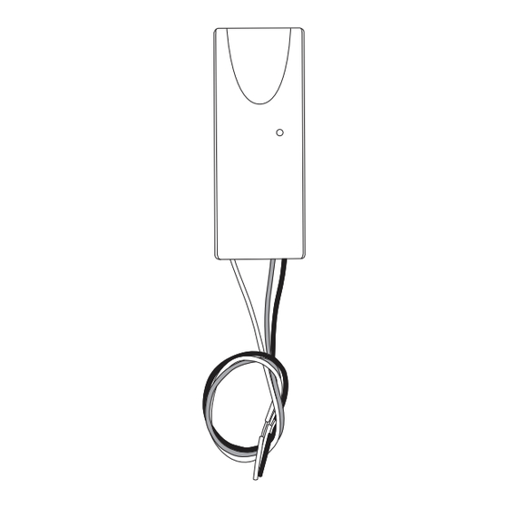
1108 DOORBELL MODULE
Installation Guide
Figure 1: 1108 Doorbell Module
DESCRIPTION
The 1108 Doorbell Module monitors
doorbell button presses. When
someone rings the doorbell, the
module sends a wireless signal
to annunciate at keypads or any
connected 1136 Wireless Sounders.
Compatibility
•
All panels with firmware Version
192 and higher
•
Any video or mechanical doorbell
with a standard transformer or a
16‑24 VAC wall transformer with
either a mechanical chime or
10 Ohm resistor in the circuit
•
7000 Series Thinline Keypads
with Level J hardware and
firmware Version 306 (1/9/18) or
higher
•
8860 Series 7‑Inch Touchscreen
Keypads
•
9000 Series Wireless Keypads
with firmware Version 201 or
higher
•
7800/9800 Series Graphic
Touchscreen Keypads with
firmware Version 110 or higher
What is Included?
•
One 1108 Doorbell Module
•
Double‑sided Tape
1
PROGRAM THE PANEL
When programming the 1108 in the panel, refer to the panel
programming guide for full programming information.
If you'll be using an 1106 Wireless Transmitter for the LED survey,
program the transmitter in the panel while referring to the
1106 Installation Guide (LT‑1377). This is because the 1108 does not
have its own LED operation.
After completing each of the following steps for the 1108, press
CMD to advance to the next prompt.
1.
Enter 6653 (PROG) at the panel keypad and go to ZONE
INFORMATION.
2.
At ZONE NO, enter the wireless zone number.
3.
At *UNUSED*, enter the zone name.
4.
At ZONE TYPE, press any select key or area and select DB
(Doorbell).
5.
At the Area Assignment section, select the area.
6.
At the NEXT ZONE prompt, select NO.
7.
When WIRELESS? displays, select YES.
8.
At SERIAL#, enter the eight‑digit device serial number. Refer
to Figure 2 for serial number location.
9.
At SUPRVSN TIME, enter a supervision time. Default is 240.
10. At the NEXT ZONE prompt, select YES if you are finished
programming the zone. Select NO if you would like to access
additional programming options.
11. To save panel programming, go to STOP and press CMD.
2
SELECT A LOCATION
To select a location, use an 1106 Series Universal Wireless
Transmitter to perform an LED survey operation.
1.
With the cover removed, hold the module in the desired
location.
2.
Press the tamper switch to send a signal to the panel and
determine if communication is confirmed or faulty.
Confirmed: For each press or release of the tamper
switch, the LED blinks immediately on and
immediately off. Repeat this test to confirm five
separate consecutive LED blinks. Any indication
otherwise means proper communication has not been
established.
Faulty: The module LED remains on for about
8 seconds or flashes multiple times in quick
succession.
3.
If the transmitter is not communicating with the panel,
start by looking for items that might cause interference,
such as metal objects or electronic equipment. Move the
transmitter or receiver and repeat the survey procedure
until communication is confirmed.
Advertisement

Related Manuals for DMP 1108

Summary of Contents for DMP 1108
- Page 1 1106 Installation Guide (LT‑1377). This is because the 1108 does not have its own LED operation. After completing each of the following steps for the 1108, press CMD to advance to the next prompt. Enter 6653 (PROG) at the panel keypad and go to ZONE INFORMATION.
- Page 2 For wiring with an installer supplied 10 Ohm 1 Watt resistor instead of a chime, refer to Figure 4. ƒ When using the 1108 with the V‑4061DB Video Doorbell, you must program the Video Doorbell for ƒ mechanical chime during setup.
- Page 3 TEST THE 1108 After the 1108 has been installed, test to confirm that it is communicating reliably with the panel. Use the Tech APP™ to perform a Wireless Check‑in Test on the system or follow these steps to perform a Wireless Check‑in Test from a keypad that is connected to the panel: At the keypad, enter 8144 (WALK) and select WLS.
- Page 4 établies par le Code de sécurité 6 de Santé Canada. Le système doit être installé à une distance minimale de 7.87 pouces (20 cm) séparant l’antenne d’une personne présente en conformité avec les limites permises d’exposition du grand public. Patents 1108 DOORBELL MODULE U.S. Patent No. 7,239,236 Specifications Certifications Primary 16 VAC - 24 VAC...
Need help?
Do you have a question about the 1108 and is the answer not in the manual?
Questions and answers