Table of Contents
Advertisement
Quick Links
Advertisement
Table of Contents
Troubleshooting

Related Manuals for Supermicro A4SAN-H


Summary of Contents for Supermicro A4SAN-H
- Page 1 A4SAN-H/-E/-L A4SAN-H/-E/-L-WOHS USER'S MANUAL Revision 1.0a (MNL-2690)
- Page 2 For more information, go to https://www.P65Warnings.ca.gov. The products sold by Supermicro are not intended for and will not be used in life support systems, medical equipment, nuclear facilities or systems, aircraft, aircraft devices, aircraft/emergency communication devices or other critical systems whose failure to perform be reasonably expected to result in significant injury or loss of life or catastrophic property damage.
- Page 3 If you have any questions, contact our support team. Region-specific Technical Support email addresses can be found at: "Contacting Supermicro" on page 9 If you have any feedback on Supermicro product manuals, contact our writing team at: Techwriterteam@supermicro.com This manual may be periodically updated without notice. Check the Supermicro website for possible updates to the manual revision level.
- Page 4 A4SAN-H/-E/-L/-WOHS: Preface Important: Important information given to ensure proper system installation or to relay safety precautions. Note: Additional Information given to differentiate various models or provides information for proper system setup.
-
Page 5: Table Of Contents
A4SAN-H/-E/-L/-WOHS: Contents Contents Contacting Supermicro Chapter 1: Introduction 1.1 Quick Reference Checklist Motherboard Layout Motherboard Mechanical Drawings Quick Reference Table System Block Diagram 1.2 Platform Overview 1.3 Special Features Recovery from AC Power Loss 1.4 System Health Monitoring Onboard Voltage Monitors... - Page 6 A4SAN-H/-E/-L/-WOHS: Contents Proper Battery Disposal Battery Installation 2.5 Connections, Jumpers, and LEDs Main Power Connector Headers and Connections CMOS Battery COM Headers Fan Header Front Panel Audio Header General Purpose I/O Header Low Voltage Differential Signaling M.2 Slots Nano SIM Card Slot...
- Page 7 A4SAN-H/-E/-L/-WOHS: Contents No Video System Boot Failure Memory Errors Losing the System's Setup Configuration When the System Becomes Unstable 3.2 Technical Support Procedures 3.3 Motherboard Battery 3.4 Where to Get Replacement Components 3.5 Returning Merchandise for Service 3.6 Feedback Chapter 4: UEFI BIOS 4.1 Introduction...
- Page 8 TLS Authenticate Configuration Menu Driver Health Menu COM Port Mode Configuration Menu 4.4 Event Logs 4.5 Thermal & Fan 4.6 Security Supermicro Security Erase Configuration Menu Secure Boot Menu 4.7 Boot 4.8 Save & Exit Appendix A: BIOS Codes BIOS Codes...
-
Page 9: Contacting Supermicro
A4SAN-H/-E/-L/-WOHS: Contacting Supermicro Contacting Supermicro Headquarters Address: Super Micro Computer, Inc. 980 Rock Ave. San Jose, CA 95131 U.S.A. Tel: +1 (408) 503-8000 Fax: +1 (408) 503-8008 Email: Marketing@supermicro.com (General Information) Sales-USA@supermicro.com (Sales Inquiries) Government_Sales-USA@supermicro.com (Gov. Sales Inquiries) Support@supermicro.com (Technical Support) RMA@Supermicro.com (RMA Support) -
Page 10: Chapter 1: Introduction
A4SAN-H/-E/-L/-WOHS: Introduction Chapter 1: Introduction Congratulations on purchasing your computer motherboard from an industry leader. Supermicro motherboards are designed to provide you with the highest standards in quality and performance. -
Page 11: Quick Reference
For details on the A4SAN- H/- E/- L/- WOHS motherboard layout, features, and other quick reference information, refer to the content below. Checklist Main Parts List (Retail Single Package) Description Part Number Quantity Supermicro Motherboard with Passive Heatsink A4SAN-H/-E/-L (-WOHS SKU does not include a heatsink) Audio Cable (line-out, mic-in) CBL-OTHR-0986 COM Cable CBL-CDAT-0665... -
Page 12: Motherboard Layout
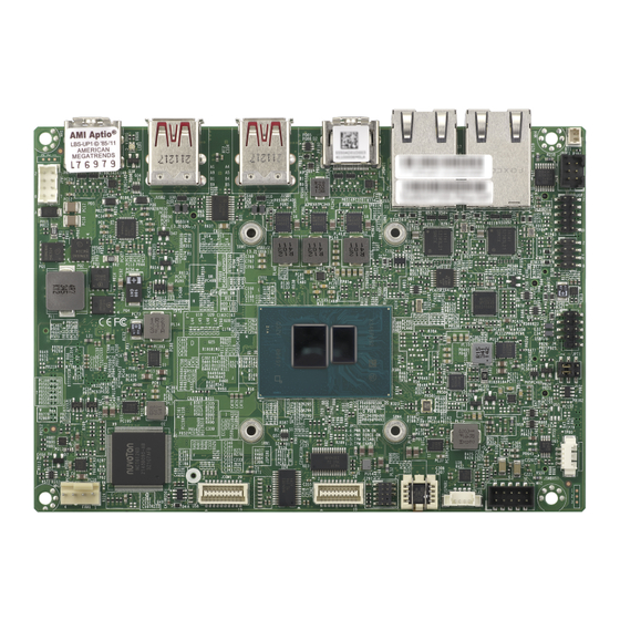
A4SAN-H/-E/-L/-WOHS: Introduction Motherboard Layout Figure 1-1. A4SAN-H/-E/-L/-WOHS Motherboard Top Photo... - Page 13 A4SAN-H/-E/-L/-WOHS: Introduction Figure 1-2. A4SAN-H/-E/-L-WOHS Motherboard Bottom Photo...
- Page 14 A4SAN-H/-E/-L/-WOHS: Introduction Figure 1-3. A4SAN-H/-E/-L/-WOHS Motherboard Top Layout...
- Page 15 A4SAN-H/-E/-L/-WOHS: Introduction Figure 1-4. A4SAN-H/-E/-L/-WOHS Motherboard Bottom Layout Notes: "Component Installation" on page 32 for detailed information on jumpers, connectors, and LED indicators. "■" indicates the location of pin 1. Components not documented are for internal testing only. Use only the correct type of onboard CMOS battery as specified by the manufacturer.
-
Page 16: Motherboard Mechanical Drawings
A4SAN-H/-E/-L/-WOHS: Introduction Motherboard Mechanical Drawings Figure 1-5. A4SAN-H/-E/-L Top Layout Mechanical Drawing Figure 1-6. A4SAN-H/-E/-L Bottom Layout Mechanical Drawing... - Page 17 A4SAN-H/-E/-L/-WOHS: Introduction Figure 1-7. A4SAN-H/-E/-L Back Panel Mechanical Drawing Figure 1-8. A4SAN-H/-E/-L/-WOHS Back Panel Mechanical Drawing...
-
Page 18: Quick Reference Table
A4SAN-H/-E/-L/-WOHS: Introduction Quick Reference Table Jumper Description Default Settings JLCDPWR1 LVDS Panel VCC Power 3.3 V/5 V Pins 1–3 (3.3 V) CMOS Clear Pins 1–3 (Normal) JPME2 ME Manufacturing Mode Pins 4–6 (Normal) Onboard TPM 2.0 Enable/Disable Pins 1–3 (Enabled) - Page 19 Power LED Red: S5 or main power fail Off: System off Motherboard Features ® ® A4SAN-H/-WOHS supports an Intel Atom Processor x7835RE A4SAN-E/-WOHS supports an Intel Atom Processor x7433RE A4SAN-L/-WOHS supports an Intel Processor N97 Memory Supports up to 16 GB of Non-ECC DDR5 SO-DIMM with speeds of up to 4800 MT/s in a...
- Page 20 A4SAN-H/-E/-L/-WOHS: Introduction Motherboard Features Graphics Intel Gen12 UHD Graphics: up to 32EUs, GFX SR-IOV, 4K at 60Hz, Open GL 4.6, DirectX 12.1, Vulkan 1.2, Mesa 3D, Open GL 4.6 Hardware Accelerated Video Decode: MPEG2, WMV9 (VC1), AVC/H264, JPEG/MJPEG, HEVC/H265, VP9, AV1 Hardware Accelerated Video Encode: MPEG2, AVC/H264, JPEG, HEVC/H265, VP9 Display: Dual HDMI 1.4b (resolution up to 4096 x 2160 at 24 Hz), LVDS (dual channel 48-bit,...
- Page 21 Supermicro Update Manager SUM (InBand) Watchdog Timer LED Indicators Power/Suspend-state Indicator LED HDD Activity LED Dimensions 3.5" x 4" (L) x 5.75" (W) (102 mm x 146 mm) SBC Total Height: 1.09" (27.8 mm) (A4SAN-H/-E/-L) Total Height: 1.07" (27.22 mm) (A4SAN-H/-E/-L/-WOHS)
- Page 22 Motherboard Features Environment Operating Temperature Range: A4SAN-H/-E supports -40°C to 60°C (-40°F to 40°F) 70C support by request A4SAN-L supports 0°C to 60°C (32°F to 140°F) A4SAN-H/-E/-WOHS supports -40°C to 85°C (-22°F to 185°F) A4SAN-L/-WOSH supports 0°C to 85°C (32°F to 185°F) Non-Operating Temperature Range: -40°C to 85°C (-40°F to 185°F)
- Page 23 A4SAN-H/-E/-L/-WOHS: Introduction A4SAN Series Specification Chart Operating Thermal Model Functions Temperature Solution Two 2.5 GbE with PoE -40°C to 60°C A4SAN-H X7835RE Two HDMI 1.4 Note: 70°C support One 48-bit LVDS Passive by request Two RS-232/422/485 A4SAN-E X7433RE Two RS-232 Four USB 3.1 Gen2 Type-A...
-
Page 24: System Block Diagram
A4SAN-H/-E/-L/-WOHS: Introduction System Block Diagram Figure 1-9. A4SAN System Block Diagram... -
Page 25: Platform Overview
Directed I/O (Intel VT-d) Intel Smart Sound Technology, Intel High-Definition Audio The A4SAN-H/-E/-L motherboard is a 3.5" Single Board Computer (4.01" x 5.75") powered by the Intel Processor N Series and the Intel Atom X7000 series processors. These processors have a core configuration of up to 8 cores and an Intel UHD Graphics Gen12 with up to 32 EUs. - Page 26 The A4SAN supports a wide range of 9 V to 36 V DC input power to meet various embedded system requirements, such as transportation and medical applications. Based on numerous demands from embedded applications, Supermicro developed an optimized thermal solution for A4SAN, producing a fanless design on a rugged embedded system.
-
Page 27: Special Features
A4SAN-H/-E/-L/-WOHS: Introduction 1.3 Special Features Recovery from AC Power Loss The Basic I/O System (BIOS) provides a setting that determines how the system will respond when AC power is lost and then restored to the system. You can choose for the system to remain powered off (in which case you must press the power switch to turn it back on), or for it to automatically return to the power-on state. -
Page 28: System Health Monitoring
A4SAN-H/-E/-L/-WOHS: Introduction 1.4 System Health Monitoring Onboard Voltage Monitors An onboard voltage monitor will continuously scan the voltages of the onboard chipset, memory, processor, and battery. Once a voltage becomes unstable, a warning is given or an error message is sent to the screen. The user can adjust the voltage thresholds to define the sensitivity of the voltage monitor. -
Page 29: Acpi Features
Plug and Play, an operating system- independent interface for configuration control. ACPI leverages the Plug and Play BIOS data structures while providing a processor architecture-independent implementation that is compatible with appropriate Windows operating systems. For detailed information regarding OS support, refer to the Supermicro website. -
Page 30: Power Supply
A4SAN-H/-E/-L/-WOHS: Introduction 1.6 Power Supply As with all computer products, a stable power source is necessary for proper and reliable operation. This is even more important for processors that have high CPU clock rates. In areas where noisy power transmission is present, you may choose to install a line filter to shield the computer from noise. -
Page 31: Super I/O
A4SAN-H/-E/-L/-WOHS: Introduction 1.7 Super I/O The Super I/O provides four high-speed, 16550 compatible universal asynchronous receiver- transmitter (UART) serial communication ports. Each UART includes a 128 byte send-receive FIFO, a programmable baud rate generator, complete modem control capability, and a processor interrupt system. -
Page 32: Chapter 2: Component Installation
Component Installation This chapter provides instructions on installing and replacing main system components for the A4SAN-H/-E/-L/-WOHS motherboard. To prevent compatibility issues, only use components that match the specifications and/or part numbers given. Installation or replacement of most components require that power first be removed from the... -
Page 33: Static-Sensitive Devices
A4SAN-H/-E/-L/-WOHS: Component Installation 2.1 Static-Sensitive Devices Electrostatic Discharge (ESD) can damage electronic components. To avoid damaging your motherboard, it is important to handle it very carefully. The following measures are generally sufficient to protect your equipment from ESD. Precautions Use a grounded wrist strap designed to prevent static discharge. -
Page 34: Motherboard Installation
Some components are very close to the mounting holes. Take precautionary measures to avoid damaging these components when installing the motherboard to the chassis. For a detailed diagram of the A4SAN-H/-E/-L/-WOHS motherboard, see the layout under Quick Reference. Installing the Motherboard 1. - Page 35 A4SAN-H/-E/-L/-WOHS: Component Installation 2. Locate the mounting holes on the motherboard. See Motherboard Installation for the location. Figure 2-3. Locate the Mounting Holes 3. Locate the matching mounting holes on the chassis. Align the mounting holes on the motherboard against the mounting holes on the chassis.
-
Page 36: Memory Support And Installation
Warning! Exercise extreme care when installing or removing memory modules to prevent any damage. The A4SAN-H/-E/-L/-WOHS motherboard supports up to 16 GB of Non-ECC DDR5 SO-DIMM memory with speeds of up to 4800 MT/s in a single slot. SO-DIMM Installation 1. - Page 37 A4SAN-H/-E/-L/-WOHS: Component Installation 2. Insert the SO-DIMM module vertically at about a 45 degree angle. Press down until the module locks into place. Figure 2-6. Insert at a 45 degree angle 3. The side clips will automatically secure the SO-DIMM module, locking it into place.
-
Page 38: So-Dimm Removal
A4SAN-H/-E/-L/-WOHS: Component Installation SO-DIMM Removal Push the side clips at the end of the slot to release the SO-DIMM module. Pull the SO-DIMM module up to remove it from the slot. For a detailed diagram of the A4SAN- H/- E/- L/- WOHS motherboard, see the layout under... -
Page 39: Battery Removal And Installation
A4SAN-H/-E/-L/-WOHS: Component Installation 2.4 Battery Removal and Installation Battery Removal To remove the battery, follow the steps below: 1. Power off your system and unplug your power cable. 2. Remove the battery cable at the BT1 connector on the board. - Page 40 A4SAN-H/-E/-L/-WOHS: Component Installation the heatsink. Warning! When replacing a battery, be sure to only replace it with the same type.
-
Page 41: Connections, Jumpers, And Leds
+9 V–36 V 5–8 Headers and Connections For information about the headers of the A4SAN-H/-E/-L/-WOHS motherboard, refer to the following content. CMOS Battery BT1 is a 2-pin header for an external battery. This connector is also used to clear the CMOS. -
Page 42: Com Headers
A4SAN-H/-E/-L/-WOHS: Component Installation COM Headers There are four COM ports: JCOM1 with support for two RS232/422/485 connections and JCOM2 with support for two RS232 connections. The manufacturer of the header is ACES Electronics, MPN 50419- 02001. The mapping plug header for cable assembly is 50420- 020KHK0-001. - Page 43 A4SAN-H/-E/-L/-WOHS: Component Installation COM Port Pin Definitions COM Port Pin (JCOM1, JCOM2) Definitions (COM3/COM4) Pin Definitions: 19 Total Pin Definitions: 20 Total RS422/485 RS485 Pin# RS232 Full Duplex Half Duplex Pin# RS232 SP_DCD1 TX-1 Data-1 SP_DCD3 SP_DSR1 SP_DSR3 SP_RXD1 TX+1...
-
Page 44: Fan Header
A4SAN-H/-E/-L/-WOHS: Component Installation COM Port Pin Definitions COM Port Pin (D-SUB from CBL-DAT-0665) Definitions (D-SUB from CBL-CDAT- Pin Definitions: 20 Total 0665) RS422/485 RS485 Pin# RS232 Pin Definitions: 20 Total Full Duplex Half Duplex Pin# RS232 SP_DCD1 TX-1 Data-1 SP_DCD3... -
Page 45: Front Panel Audio Header
A4SAN-H/-E/-L/-WOHS: Component Installation For a detailed diagram of the A4SAN- H/- E/- L/- WOHS motherboard, see the layout under "Quick Reference" on page 4-pin Fan Header Pin Definitions: Four Total Pin# Definition GND (Black) +12 V (Red) Tachometer PWM Control... -
Page 46: Low Voltage Differential Signaling
A4SAN-H/-E/-L/-WOHS: Component Installation GPIO Header Pin Definitions: 10 Total Pin# Description Pin# Description P3V3SB GP_P3V3_GP0 GP_P3V3_GP4 GP_P3V3_GP1 GP_P3V3_GP5 GP_P3V3_GP2 GP_P3V3_GP6 GP_P3V3_GP3 GP_P3V3_GP7 Low Voltage Differential Signaling LVDS1 on the bottom side of the motherboard is the LVDS connector. Low-voltage differential signaling (LVDS) is a high-speed digital interface that operates at low power. -
Page 47: Slots
A4SAN-H/-E/-L/-WOHS: Component Installation LVDS Connector Pin Definitions: 40 Total Pin# Description Pin# Descritption LVDSB D0N LVDSB D0P LVDSB D1N LVDSB D1P LVDSB D2N LVDSB D2P LVDSB CLKN LVDSB CLKP LVDSB D3N LVDSB D3P M.2 Slots The motherboard has three M.2 slots (JMD1, JMD2, JMD3). M.2 was formerly known as Next Generation Form Factor (NGFF) and serves to replace mini PCIe. - Page 48 A4SAN-H/-E/-L/-WOHS: Component Installation M.2 B-Key Pin Definitions: 75 Total Pin# Definition Pin# Definition No Connection VBUS_SENSE WAKE_ON_WWAN#(PU to P1V8SB) No Connection No Connection W_DISABLE2#(PU to P1V8SB only) No Connection USB3.0-Rx- UIM-RESET USB3.0-Rx+ UIM-CLK UIM-DATA USB3.0-Tx- UIM-PWR USB3.0-Tx+ No Connection No Connection...
- Page 49 A4SAN-H/-E/-L/-WOHS: Component Installation M.2 E-Key Pin Definitions: 75 Total Pin# Definition Pin# Definition P3V3SB USB_D+ P3V3SB USB_D- No Connection CNV_BT_I2C_SCLK CNV_WR_LANE1_DN CNV_RF_RESET_N CNV_WR_LANE1_DP CNV_BT_I2S_SDO MODEM_CLKREQ CNV_WR_LANE0_DN No Connection CNV_WR_LANE0_DP UART_BT_WAKE_N CNV_WR_CLK_DN CNV_BRI_RSP CNV_WR_CLK_DP KEY E KEY E KEY E KEY E...
- Page 50 A4SAN-H/-E/-L/-WOHS: Component Installation M.2 E-Key Pin Definitions: 75 Total Pin# Definition Pin# Definition No Connection CNV_WT_LANE1_DN No Connection CNV_WT_LANE1_DP No Connection No Connection CNV_WT_LANE0_DN No Connection CNV_WT_LANE0_DP No Connection No Connection CNV_WT_CLK_DN P3V3SB CNV_WT_CLK_DP P3V3SB M.2 M-Key Pin Definitions: 75 Total...
-
Page 51: Nano Sim Card Slot
A4SAN-H/-E/-L/-WOHS: Component Installation M.2 M-Key Pin Definitions: 75 Total Pin# Definition Pin# Definition No Connection No Connection No Connection No Connection No Connection No Connection No Connection No Connection SATA-B+/PERn0 No Connection SATA-B-/PERp0 No Connection No Connection SATA-A-/PETn0 No Connection... -
Page 52: Smbus Header
A4SAN-H/-E/-L/-WOHS: Component Installation SMBus Header A System Management Bus header for additional slave devices or sensors is located at JSMBUS1. For a detailed diagram of the A4SAN- H/- E/- L/- WOHS motherboard, see the layout under "Quick Reference" on page... -
Page 53: Usb 3.2 Port
These connectors are designed specifically for use with the Supermicro chassis. See the figure below for the descriptions of the front control panel buttons and LED indicators. -
Page 54: Power Button
A4SAN-H/-E/-L/-WOHS: Component Installation Power Button The Power Button connection is located on pins 1 and 2 of JF1 on the A4SAN-H/-E/-L/-WOHS motherboard. Momentarily contacting both pins will power on/off the system. This button can also be configured to function as a suspend button (with a setting in the BIOS). To turn off the power when the system is in suspend mode, press the button for four seconds or longer. -
Page 55: Power Led
A4SAN-H/-E/-L/-WOHS: Component Installation HDD LED Pin Definitions (JF1) Pin# Definition 3.3 V HDD LED Power LED The Power LED connection is located at pins 7 and 8 of JF1. Refer to the table below for pin definitions. Power LED Pin Definitions (JF1) -
Page 56: Jumper Settings
A4SAN-H/-E/-L/-WOHS: Component Installation Jumper Settings To modify the operation of the motherboard, jumpers can be used to choose between optional settings. Jumpers create shorts between two pins to change the function of the connector. Pin 1 is identified with a square solder pad on the printed circuit board. See the diagram below for an example of jumping pins 1 and 2. -
Page 57: Sim Detect Option
A4SAN-H/-E/-L/-WOHS: Component Installation setting is Normal. For a detailed diagram of the A4SAN- H/- E/- L/- WOHS motherboard, see the layout under "Quick Reference" on page ME Manufacturing Mode Jumper Settings Jumper Setting Definition Pins 2–4 Manufacturing Mode Pins 4–6... -
Page 58: Led Indicators
Onboard Power LED The Onboard Power LED is located at on the A4SAN-H/-E/-L/-WOHS motherboard. When this LED is on, the system is on. Be sure to turn off the system and unplug the power cord before removing or installing components. -
Page 59: Chapter 3: Troubleshooting
A4SAN-H/-E/-L/-WOHS: Troubleshooting Chapter 3: Troubleshooting The following content contains information on common issues and how to resolve them. -
Page 60: Troubleshooting Procedures
A4SAN-H/-E/-L/-WOHS: Troubleshooting 3.1 Troubleshooting Procedures Use the following procedures to troubleshoot your system. If you have followed all of the procedures below and still need assistance, refer to the "Technical Support Procedures" on page 64 "Returning Merchandise for Service" on page 67 section(s) in this chapter. -
Page 61: System Boot Failure
A4SAN-H/-E/-L/-WOHS: Troubleshooting System Boot Failure If the system does not display Power-On-Self-Test (POST) or does not respond after the power is turned on, or LED1 is red, do the following: 1. Check the screen for an error message. 2. Clear the CMOS settings by unplugging the power cord and contacting both pads on the CMOS clear jumper. -
Page 62: When The System Becomes Unstable
BIOS installed in your system. 2. Memory support: Make sure that the memory modules are supported. Refer to the product page on our website at https://www.supermicro.com. Test the modules using memtest86 or a similar utility. Note: Click on the "Tested Memory List" link on the motherboard's product page to see a list of supported memory. - Page 63 A4SAN-H/-E/-L/-WOHS: Troubleshooting 4. Identifying bad components by isolating them: If necessary, remove a component in question from the chassis, and test it in isolation to make sure that it works properly. Replace a bad component with a good one. 5. Check and change one component at a time instead of changing several items at the same time.
-
Page 64: Technical Support Procedures
Before contacting Technical Support, take the following steps. Also, note that as a motherboard manufacturer, Supermicro also sells motherboards through its channels, so it is best to first check with your distributor or reseller for troubleshooting services. They should know of any possible problems with the specific system configuration that was sold to you. -
Page 65: Motherboard Battery
A4SAN-H/-E/-L/-WOHS: Troubleshooting 3.3 Motherboard Battery For information on removing, disposing of, and replacing the motherboard battery of your system, refer to "Battery Removal and Installation" on page... -
Page 66: Where To Get Replacement Components
A4SAN-H/-E/-L/-WOHS: Troubleshooting 3.4 Where to Get Replacement Components If you need replacement parts for your A4SAN-H/-E/-L/-WOHS motherboard, to ensure the highest level of professional service and technical support, purchase exclusively from our Supermicro Authorized Distributors/System Integrators/Resellers. A list can be found at... -
Page 67: Returning Merchandise For Service
(https://www.supermicro.com/RmaForm). Whenever possible, repack the motherboard in the original Supermicro carton, using the original packaging material. If these are no longer available, be sure to pack the motherboard securely, using packaging material to surround the motherboard so that it does not shift within the carton and become damaged during shipping. -
Page 68: Feedback
A4SAN-H/-E/-L/-WOHS: Troubleshooting 3.6 Feedback Supermicro values your feedback as we strive to improve our customer experience in all facets of our business. Email us at Techwriterteam@supermicro.com to provide feedback on our manuals. -
Page 69: Chapter 4: Uefi Bios
A4SAN-H/-E/-L/-WOHS: UEFI BIOS Chapter 4: UEFI BIOS The following content contains information on BIOS configuration with the A4SAN-H/-E/-L/- WOHS motherboard. -
Page 70: Introduction
A4SAN-H/-E/-L/-WOHS: UEFI BIOS 4.1 Introduction This chapter describes the AMIBIOS™ Setup utility for the motherboard. The BIOS is stored on a chip and can be easily upgraded using a flash program. Note: Due to periodic changes to the BIOS, some settings may have been added or deleted and might not yet be recorded in this manual. - Page 71 A4SAN-H/-E/-L/-WOHS: UEFI BIOS selected in the left frame, it is highlighted in white. Often a text message accompany it. (Note that BIOS has default text messages built in. We retain the option to include, omit, or change any of these text messages.) Settings printed in Bold are the default values.
-
Page 72: Main Setup
A4SAN-H/-E/-L/-WOHS: UEFI BIOS 4.2 Main Setup When you first enter the AMI BIOS Setup utility, you enter the Main setup screen. You can always return to the Main setup screen by selecting the Main tab on the top of the screen. The... - Page 73 A4SAN-H/-E/-L/-WOHS: UEFI BIOS Figure 4-1. Main Setup System Date/System Time Use the two features to change the system date and time. Highlight System Date or System Time using the arrow keys. Enter new values using the keyboard. Press the <Tab> key or the arrow keys to move between fields.
- Page 74 A4SAN-H/-E/-L/-WOHS: UEFI BIOS Memory Information Total Memory This feature displays the total size of memory available in the system.
-
Page 75: Advanced Setup Configurations
A4SAN-H/-E/-L/-WOHS: UEFI BIOS 4.3 Advanced Setup Configurations Use the arrow keys to select the Advanced submenu and press <Enter> to access the submenu items. Figure 4-2. Advanced Setup Configurations Warning! Take caution when changing the Advanced settings. An incorrect value, an improper DRAM frequency, or a wrong BIOS timing setting may cause the system to malfunction. -
Page 76: Acpi Settings Menu
A4SAN-H/-E/-L/-WOHS: UEFI BIOS ACPI Settings Menu ►ACPI Settings ACPI Sleep State Use this feature to select the ACPI Sleep State that the system will enter into when the suspend button is activated. The options are Suspend Disabled and S3 (Suspend to RAM). -
Page 77: Boot Feature Menu
A4SAN-H/-E/-L/-WOHS: UEFI BIOS Boot Feature Menu ►Boot Feature Fast Boot Enable this feature to reduce the time the computer takes to boot up. The computer will boot with a minimal set of required devices. This feature does not have an effect on BBS boot options in the Boot tab. -
Page 78: Cpu Configuration Menu
A4SAN-H/-E/-L/-WOHS: UEFI BIOS Power Button Function This feature controls how the system shuts down when the power button is pressed. Select 4 Seconds Override to power off the system after pressing and holding the power button for four seconds or longer. Select Instant Off to instantly power off the system as soon as you press the power button. - Page 79 A4SAN-H/-E/-L/-WOHS: UEFI BIOS EIST Technology CPU C3 state CPU C6 state CPU C7 state CPU C8 state CPU C9 state CPU C10 state Performance L1 Data Cache Performance L1 Instruction Cache Performance L2 Cache Performance L3 Cache Efficient L1 Data Cache...
- Page 80 A4SAN-H/-E/-L/-WOHS: UEFI BIOS Note: Please reboot the system for any change of the setting to take effect. Active Efficient-cores This feature determines how many efficient cores will be activated for each processor package. When all is selected, all cores in the processor will be activated. The options are All, 3, 2, 1, and 0.
- Page 81 A4SAN-H/-E/-L/-WOHS: UEFI BIOS Power Limit 2 Override Select Enabled to support rapid power limit (PL2) override. The options are Disabled and Enabled. Power Limit 2 Use this feature to configure the value for Power Limit 2. The value is in milliwatts and the step size is 125 mW.
-
Page 82: Chipset Configuration Menu
A4SAN-H/-E/-L/-WOHS: UEFI BIOS Monitor MWAIT Select Enabled to support Monitor and Mwait, which are two instructions in Streaming SIMD Extension 3 (SSE3) to improve synchronization between multiple threads for CPU performance enhancement. The options are Disabled and Enabled. ® Intel TCC Mode Use this feature to enable or disable the Intel Time Coordinated Computing (TCC) Mode. -
Page 83: Graphics Configuration Menu
A4SAN-H/-E/-L/-WOHS: UEFI BIOS Maximum Memory Frequency Use this feature to set the maximum memory frequency for onboard memory modules. The options are Auto, 1600, 1800, 2000, 2200, 2400, 2600, 2800, 3000, 3200, 3600, 4000, 4200, 4400, 4600, and 4800. Max TOLUD This feature sets the maximum TOLUD value, which specifies the "Top of Low Usable DRAM"... - Page 84 A4SAN-H/-E/-L/-WOHS: UEFI BIOS Graphics Configuration IGFX GOP Version Graphics Turbo IMON Current Use this feature to set the graphics turbo IMON value. The default is 31. Skip Scanning of External Gfx Card If this feature is enabled, the system will not scan for an external graphics card on PEG and PCIe slots.
-
Page 85: Dmi/Opi Configuration Menu
A4SAN-H/-E/-L/-WOHS: UEFI BIOS Graphics Clock Frequency Use this feature to set the internal graphics clock frequency. The options are 192 Mhz, 307.2 Mhz, 556.8 Mhz, 652.8 MHZ, and Max CdClock freq based on Reference Clk. DMI/OPI Configuration Menu ►DMI/OPI Configuration This submenu allows you to configure the DMI/OPI configuration settings. - Page 86 A4SAN-H/-E/-L/-WOHS: UEFI BIOS ►PCIe M.2-E1 PCIe M.2-E1 ASPM Use this feature to activate the Active State Power Management (ASPM) level for a PCIe device. Select Auto for the system BIOS to automatically set the ASPM level based on the system configuration. Select Disabled to disable ASPM support. The options are Disabled, L1, and Auto.
-
Page 87: Hdd Security Configuration
A4SAN-H/-E/-L/-WOHS: UEFI BIOS ►PCIe M.2-B1 PCIe M.2-B1 ASPM Use this feature to activate the Active State Power Management (ASPM) level for a PCIe device. Select Auto for the system BIOS to automatically set the ASPM level based on the system configuration. Select Disabled to disable ASPM support. The options are Disabled, L1, and Auto. -
Page 88: Gpio Expander Header
A4SAN-H/-E/-L/-WOHS: UEFI BIOS Panel Color Depth Use this feature to select the LFP panel color depth. The options are Disabled, VESA and JEIDA18 bpp, VESA 24 bpp, and JEIDA 24 bpp. Backlight Brightness Use this feature to select panel backlight brightness. The options are from 7% to 100%. -
Page 89: Http Boot Configuration Menu
(WARNING: Security Risk!). Warning! Disabling "HTTP Boot Checks Hostname" is a violation of RFC 6125 and may expose you to Man-in-the-Middle Attacks. Supermicro is not responsible for any and all security risks incurred by you disabling this feature. Priority of HTTP Boot Instance of Priority 1: (Available when your motherboard supports this feature) This feature sets the rank target port. -
Page 90: Nct6126 Super Io Configuration
A4SAN-H/-E/-L/-WOHS: UEFI BIOS NCT6126 Super IO Configuration NCT6126D Super IO Configuration The following information is displayed. Super IO Chip Serial Port 1 Configuration Menu ►Serial Port 1 Configuration Serial Port 1 Select Enabled to enable serial port 1. The options are Disabled and Enabled. -
Page 91: Serial Port 4 Configuration Menu
A4SAN-H/-E/-L/-WOHS: UEFI BIOS Serial Port 4 Configuration Menu ►Serial Port 4 Configuration Serial Port 4 Select Enabled to enable serial port 4. The options are Disabled and Enabled. Device Settings (Available when "Serial Port 4" above is set to Enabled) This feature shows the base I/O port address and the Interrupt Request address of serial port 2. -
Page 92: Mac:(Mac Address)-Ipv4 Network Configuration Menu
A4SAN-H/-E/-L/-WOHS: UEFI BIOS Media Detect Count (Available when "Network Stack" is set to Enabled) Use this feature to set the wait time (in seconds) for the BIOS ROM to detect the presence of a LAN media either via the Internet connection or via a LAN port. Press the <+> or <-> key on your keyboard to change the value. - Page 93 A4SAN-H/-E/-L/-WOHS: UEFI BIOS Interface Name Interface Type MAC address Host address Route Table Gateway addresses DNS addresses Interface ID Use this feature to change/enter the 64-bit alternative interface ID for the device. The string format is colon separated. The default setting is the MAC address above.
-
Page 94: Pch-Fw Configuration Menu
A4SAN-H/-E/-L/-WOHS: UEFI BIOS PCH-FW Configuration Menu The following information is displayed. ME Firmware Version ME Firmware Mode ME Firmware SKU ME FW Image Re-Flash Use this feature to update the Management Engine firmware. The options are Disabled and Enabled. TPM Device Selection Use this feature to select dTPM or PTT for the TPM device. - Page 95 A4SAN-H/-E/-L/-WOHS: UEFI BIOS SR-IOV Support Use this feature to enable or disable Single Root IO Virtualization Support. The options are Disabled and Enabled. BME DMA Mitigation Enable this feature to help block DMA attacks. The options are Disabled and Enabled.
- Page 96 A4SAN-H/-E/-L/-WOHS: UEFI BIOS PCI / PCIX / PCIe Slot 7 OPROM Use this feature to enable or disable the PCI/PCIX/PCIe slot 7 OPROM option. The options are Disabled and EFI. PCI / PCIX / PCIe Slot 8 OPROM Use this feature to enable or disable the PCI/PCIX/PCIe slot 8 OPROM option. The options are Disabled and EFI.
-
Page 97: Sata And Rst Configuration Menu
A4SAN-H/-E/-L/-WOHS: UEFI BIOS SATA and RST Configuration Menu SATA And RST Configuration SATA Controller(s) Use this feature to enable or disable the onboard SATA controller supported by the Intel PCH chip. The options are Enabled and Disabled. Storage Option ROM/UEFI Driver Select UEFI to load the EFI driver for system boot. - Page 98 A4SAN-H/-E/-L/-WOHS: UEFI BIOS ►COM1 Console Redirection Settings COM1 Console Redirection Settings COM1 Console Redirection Settings (Available if "COM1 Console Redirection" is set to Enabled.) Use this feature to specify how the host computer will exchange data with the client computer, which is the remote computer.
- Page 99 A4SAN-H/-E/-L/-WOHS: UEFI BIOS COM1 VT-UTF8 Combo Key Support Select Enabled to enable VT-UTF8 Combination Key support for ANSI/VT100 terminals. The options are Disabled and Enabled. COM1 Recorder Mode Select Enabled to capture the data displayed on a terminal and send it as text messages to a remote server.
- Page 100 A4SAN-H/-E/-L/-WOHS: UEFI BIOS support. Select ANSI to use the Extended ASCII Character Set. Select VT-UTF8 to use UTF8 encoding to map Unicode characters into one or more bytes. The options are VT100, VT100+, VT-UTF8, and ANSI. COM2 Bits Per Second Use this feature to set the transmission speed for a serial port used in Console Redirection.
- Page 101 A4SAN-H/-E/-L/-WOHS: UEFI BIOS COM2 Putty KeyPad This feature selects the settings for Function Keys and KeyPad used for Putty, which is a terminal emulator designed for the Windows OS. The options are VT100, LINUX, XTERMR6, SC0, ESCN, and VT400. COM2 Redirection After BIOS POST Use this feature to enable or disable legacy console redirection after BIOS POST.
- Page 102 A4SAN-H/-E/-L/-WOHS: UEFI BIOS COM3 Parity A parity bit can be sent along with regular data bits to detect data transmission errors. Select Even if the parity bit is set to 0, and the number of 1's in data bits is even. Select Odd if the parity bit is set to 0, and the number of 1's in data bits is odd.
- Page 103 A4SAN-H/-E/-L/-WOHS: UEFI BIOS COM4 COM4 Console Redirection Select Enabled to enable console redirection support for a serial port. The options are Enabled and Disabled. ►COM4 Console Redirection Settings COM4 Console Redirection Settings COM4 Console Redirection Settings (Available if "COM1 Console Redirection" is set to Enabled.)
- Page 104 A4SAN-H/-E/-L/-WOHS: UEFI BIOS COM4 Flow Control Use this feature to set the flow control for Console Redirection to prevent data loss caused by buffer overflow. Send a "Stop" signal to stop sending data when the receiving buffer is full. Send a "Start" signal to start sending data when the receiving buffer is empty. The options are None and Hardware RTS/CTS.
-
Page 105: Trusted Computing Menu
A4SAN-H/-E/-L/-WOHS: UEFI BIOS Out-of-Band Mgmt Port The feature selects a serial port in a client server to be used by the Microsoft Windows Emergency Management Services (EMS) to communicate with a remote host server. The options are COM1 and SOL/COM2. Please note that the option of SOL/COM2 indicates a shared serial port. - Page 106 A4SAN-H/-E/-L/-WOHS: UEFI BIOS TPM 2.0 Device Found Firmware Version: Vendor: Security Device Support Select Enabled to enable BIOS support for onboard security devices, which are not displayed in the OS. If this feature is set to Enabled, TCG EFI protocol and INT1A interface will not be available.
-
Page 107: Usb Configuration Menu
A4SAN-H/-E/-L/-WOHS: UEFI BIOS Storage Hierarchy (Available when "Security Device Support" is set to Enabled and the TPM 2.0 module is detected by the BIOS) Select Enabled for TPM Storage Hierarchy support that is intended to be used for non-privacy- sensitive operations by a platform owner such as an IT professional or the end user. Storage Hierarchy has an owner policy and an authorization value, both of which can be set and are held constant (-rarely changed) through reboots. -
Page 108: Intel(R) Ethernet Controller Menu
A4SAN-H/-E/-L/-WOHS: UEFI BIOS USB S5 Wakeup Support Use this feature to enable or disable USB S5 Wakeup support. The options are Disabled and Enabled. Intel(R) Ethernet Controller Menu ►Intel(R) Ethernet Controller (I226-IT) - (XX:XX:XX:XX:XX:XX) Notes: The Ethernet controller and MAC addresses shown above are based on you system features. -
Page 109: Tls Authenticate Configuration Menu
A4SAN-H/-E/-L/-WOHS: UEFI BIOS TLS Authenticate Configuration Menu ►TLS Authenticate Configuration This submenu allows you to configure Transport Layer Security (TLS) settings. ►Server CA Configuration This feature allows you to configure the client certificate that is to be used by the server. -
Page 110: Com Port Mode Configuration Menu
A4SAN-H/-E/-L/-WOHS: UEFI BIOS Note: This section is provided for reference only, for the driver health status will differ depending on the drivers installed in your system. It's also based on your system configuration and the environment that your system is operating in. -
Page 111: Event Logs
A4SAN-H/-E/-L/-WOHS: UEFI BIOS 4.4 Event Logs Use this menu to configure Event Logs settings. Note: After you've made any changes in this section, please be sure to reboot the system for the changes to take effect. Figure 4-3. Event Logs ►Change SMBIOS Event Log Settings... - Page 112 A4SAN-H/-E/-L/-WOHS: UEFI BIOS Erasing Settings Erase Event Log (Available when "SMBIOS Event Log" is set to Enabled) Select No to keep the event log without erasing it upon next system bootup. Select (Yes, Next reset) to erase the event log upon next system reboot. The options are No, (Yes, Next reset), and (Yes, Every reset).
-
Page 113: Thermal & Fan
A4SAN-H/-E/-L/-WOHS: UEFI BIOS 4.5 Thermal & Fan Use this menu to configure Fan settings. Figure 4-4. Thermal & Fan The following information is displayed. Temperature Peripheral Temperature System Temperature CPU Temperature PCH Temperature Fan Speed FAN1 Voltage... - Page 114 A4SAN-H/-E/-L/-WOHS: UEFI BIOS PVDD2 P12V P3V3SB P3V_BAT P3V3 PVCCCORE P1V8SB P1V05_PROC ►Fan Control Fan Control Settings Fan Speed Control Mode Use this feature to select the fan speed control mode. The options are Quiet, Stable, Full Speed, and Customize. FAN1 Control FAN1 Reference sensor (Available when "Fan Speed Control Mode"...
- Page 115 A4SAN-H/-E/-L/-WOHS: UEFI BIOS Temperature 4 PWM4...
-
Page 116: Security
A4SAN-H/-E/-L/-WOHS: UEFI BIOS 4.6 Security This menu allows you to configure the following security settings for the system. Figure 4-5. Security Disable Block Sid and Freeze Lock (Available when your storage devices support TCG) Select Enabled to allow SID authentication to be performed in TCG storage devices. The options are Disabled and Enabled. -
Page 117: Supermicro Security Erase Configuration Menu
Note: This submenu is available when any storage device is detected by the BIOS. For more information about this feature, please refer to our website. This submenu allows you to configure the Supermicro- proprietary Security Erase settings. When this submenu is selected, the following information is displayed. Please note that the order of the following information may differ based on the storage devices being detected. -
Page 118: Secure Boot Menu
New Password (Available when "Password" above has been set) Use this feature to set the new user password for the storage device, which allows you to configure the Supermicro Security Erase settings by using this new user password. Secure Boot Menu ►Secure Boot... - Page 119 A4SAN-H/-E/-L/-WOHS: UEFI BIOS System Mode Secure Boot Secure Boot Select Enabled to configure Secure Boot settings. The options are Disabled and Enabled. Secure Boot Mode Use this feature to select the desired secure boot mode for the system. The options are Standard and Custom.
- Page 120 A4SAN-H/-E/-L/-WOHS: UEFI BIOS This feature resets the system to the Setup Mode. The options are Yes and No. ►Enroll Efi Image This feature allows the Efi image to run in the secure boot mode, which will enroll the SHA256 Hash certificate of a PE image into the Authorized Signature Database (DB).
- Page 121 A4SAN-H/-E/-L/-WOHS: UEFI BIOS ►Authorized TimeStamps (dbt) This feature allows you to set and save the timestamps for the Authorized Signatures, which will indicate the time when these signatures are entered into the system. These values also indicate sizes, keys, and key sources of the authorized timestamps. Select Update to update your Authorized TimeStamps.
-
Page 122: Boot
A4SAN-H/-E/-L/-WOHS: UEFI BIOS 4.7 Boot Use this menu to configure Boot settings. Figure 4-6. Boot FIXED BOOT ORDER Priorities This feature prioritizes the order of a bootable device from which the system will boot. Press <Enter> on each item sequentially to select the device. - Page 123 A4SAN-H/-E/-L/-WOHS: UEFI BIOS ►UEFI NETWORK Drive BBS Priorities This feature allows you to set the system boot order of detected devices. ►UEFI Application Boot Priorities This feature allows you to set the system boot order of detected devices.
-
Page 124: Save & Exit
A4SAN-H/-E/-L/-WOHS: UEFI BIOS 4.8 Save & Exit Select Save & Exit from the BIOS Setup screen to configure the settings below. Figure 4-7. Save & Exit Save Options Discard Changes and Exit Use this feature to exit from the BIOS Setup utility without making any permanent changes to the system configuration and reboot the computer. - Page 125 A4SAN-H/-E/-L/-WOHS: UEFI BIOS Discard Changes Select this feature and press <Enter> to discard all the changes you've made and return to the BIOS Setup utility. Default Options Restore Optimized Defaults Select this feature and press <Enter> to load manufacturer optimized default settings, which are intended for maximum system performance but not for maximum stability.
-
Page 126: Appendix A: Bios Codes
A4SAN-H/-E/-L/-WOHS: BIOS Codes Appendix A: BIOS Codes For information about BIOS codes for the A4SAN-H/-E/-L/-WOHS motherboard, refer to the following content. BIOS Codes For information about BIOS codes for the A4SAN-H/-E/-L/-WOHS motherboard, refer to the following content. BIOS Error POST (Beep) Codes During the Power-On Self-Test (POST) routines, which are performed each time the system is powered on, errors may occur. -
Page 127: Additional Bios Post Codes
A4SAN-H/-E/-L/-WOHS: BIOS Codes Additional BIOS POST Codes The AMI BIOS supplies additional checkpoint codes, which are documented online at https://www.supermicro.com/support/manuals ("AMI BIOS POST Codes User's Guide"). For information on AMI updates, refer to https://www.ami.com/products. -
Page 128: Appendix B: Software
A4SAN-H/-E/-L/-WOHS: Software Appendix B: Software After the A4SAN- H/- E/- L/- WOHS motherboard has been installed, you can install the Operating System (OS), configure RAID settings and install the drivers. -
Page 129: Microsoft Windows Os Installation
Media drive, using a USB flash or media drive, or the BMC KVM console. 2. Retrieve the proper drivers. Go to the Supermicro web page for your motherboard and click on "Download the Latest Drivers and Utilities," select the proper driver, and copy it to a USB flash drive. - Page 130 6. After the Windows OS installation has completed, the system will automatically reboot multiple times for system updates. The Supermicro website that contains drivers and utilities for your system is at https://www.supermicro.com/wdl. Some of these must be installed, such as the chipset driver.
- Page 131 A4SAN-H/-E/-L/-WOHS: Software Figure B-3. Driver Installation Screenshot Note: Click the icons showing a hand writing on paper to view the readme files for each item. Click the computer icons to the right of these items to install each item (from top to bottom) one at a time.
-
Page 132: Appendix C: Standardized Warning Statements
Should you have questions or experience difficulty, contact Supermicro's Technical Support department for assistance. Only certified technicians should attempt to install or configure components. Read this section in its entirety before installing or configuring components in the Supermicro A4SAN-H/-E/-L/-WOHS motherboard. These... - Page 133 A4SAN-H/-E/-L/-WOHS: Standardized Warning Statements WARNUNG Es besteht Explosionsgefahr, wenn die Batterie durch einen falschen Typ ersetzt wird. Ersetzen Sie die Batterie nur durch den gleichen oder vom Hersteller empfohlenen Batterietyp. Entsorgen Sie die benutzten Batterien nach den Anweisungen des Herstellers.
-
Page 134: Product Disposal
A4SAN-H/-E/-L/-WOHS: Standardized Warning Statements WAARSCHUWING Er bestaat explosiegevaar als de batterij wordt vervangen door een verkeerd type. Vervang de batterij slechts met hetzelfde of een equivalent type die door de fabrikant aanbevolen wordt. Gebruikte batterijen dienen overeenkomstig fabrieksvoorschriften afgevoerd te worden. - Page 135 A4SAN-H/-E/-L/-WOHS: Standardized Warning Statements המוצר סילוק !אזהרה המדינה וחוקי להנחיות בהתאם להיות חייב זה מוצר של סופי סילוק اﻟﯩﻄﻨﻴﺔ واﻟﻠﯩﺎﺋﺢ اﻟﻘﯩﺎﻧﻴﻦ ﻟﺠﻤﻴﻊ وﻓﻘﺎ ﻣﻌﻪ اﻟﺘﻌﺎﻣﻞ ﻳﻨﺒﻐﻲ اﻟﻤﻨﺘﺞ ﻫﺬا ﻣﻦ اﻟﻨﻬﺎﺋﻲ اﻟﺘﺨﻠﺺ ﻋﻨﺪ 경고! 이 제품은 해당 국가의 관련 법규 및 규정에 따라 폐기되어야 합니다.
Need help?
Do you have a question about the A4SAN-H and is the answer not in the manual?
Questions and answers