Table of Contents
Advertisement
MARK IV PRODUCTION / SWITCH TAMPER
OPERATION AND SERVICE MANUAL
ISSUED
2 - 2018
REVISED
10 - 2020
© 2020 HARSCO CORPORATION, ALL RIGHTS RESERVED
VARIOUS CUSTOMERS
VARIOUS SERIAL NUMBERS
WITH HYDRAULIC DRIVE - JUPITER II
CUSHMAN TRANSMISSIONS
CUMMINS QSB 6.7L TIER IV ENGINE
EC613982
BULLETIN
5082505
REVISION
C
Advertisement
Chapters
Table of Contents

Summary of Contents for Harsco MARK IV
- Page 1 MARK IV PRODUCTION / SWITCH TAMPER OPERATION AND SERVICE MANUAL VARIOUS CUSTOMERS VARIOUS SERIAL NUMBERS WITH HYDRAULIC DRIVE - JUPITER II CUSHMAN TRANSMISSIONS CUMMINS QSB 6.7L TIER IV ENGINE ISSUED 2 - 2018 EC613982 BULLETIN 5082505 REVISED 10 - 2020 REVISION ©...
- Page 2 A MANUAL MUST REMAIN WITH THE MACHINE. Additional or replacement manuals may be obtained by calling or writing Harsco Rail at any of the facility locations listed below. All information, illustrations and specifications in this manual are based on the latest information available at the time of publication.
- Page 3 TABLE OF CONTENTS SAFETY / GENERAL INFORMATION SECTION OPERATION SECTION ADJUSTMENTS SECTION MAINTENANCE SECTION TROUBLESHOOTING SECTION TORQUE / CONVERSION TABLES APPENDIX MISCELLANEOUS APPENDIX SCHEMATICS APPENDIX REVISION RECORD APPENDIX...
- Page 4 OF ITS CONSTITUENTS ARE KNOWN TO THE STATE OF CALIFORNIA TO CAUSE CANCER, BIRTH DEFECTS, AND OTHER REPRODUCTIVE HARM. EMISSION CONTROL INFORMATION MANUFACTURE DATE: CONTACT: Harsco Rail 803-822-9160 THIS EQUIPMENT HAS AN ENGINE THAT MEETS U.S. EPA EMISSION STANDARDS UNDER 40 CFR 1039.625...
- Page 5 SECTION 1 SAFETY / GENERAL INFORMATION...
- Page 6 THIS PAGE IS INTENTIONALLY BLANK...
-
Page 7: Table Of Contents
MARK IV HD J2 TAMPER SAFETY / GENERAL PAGE 1 - 1 BULLETIN 5082505 INFORMATION REVISED 10 - 2020 SECTION 1 - SAFETY / GENERAL INFORMATION TABLE OF CONTENTS Operator and Maintenance Personnel Information..... . .1 - 2 Safety Information . -
Page 8: Section 1 - Safety / General Information
THIS SYMBOL MEANS: ATTENTION! BECOME ALERT! YOUR SAFETY IS INVOLVED. SAFETY IS A CRITICAL FACTOR IN THE DESIGN OF HARSCO RAIL EQUIPMENT. THE BEST SAFETY PROGRAM STARTS WITH A SAFETY CONSCIOUS OPERATOR. THE SAFETY INFORMATION HIGHLIGHTED IN THIS BULLETIN DESCRIBES SAFE OPERATING PRACTICES FOR THE BENEFIT OF THE WORKERS WHO WILL USE OUR EQUIPMENT IN THEIR DAILY JOBS. -
Page 9: Safety Information
MARK IV HD J2 TAMPER SAFETY / GENERAL PAGE 1 - 3 BULLETIN 5082505 INFORMATION REVISED 10 - 2020 1.2.2 Safety Information STOP ENGINE WHEN FILLING FUEL TANK. DO NOT FILL FUEL TANK OR ■ ADJUST FUEL SYSTEM NEAR AN OPEN FLAME, SPARKS OR WHEN SMOKING. - Page 10 PAGE 1 - 4 SAFETY / GENERAL MARK IV HD J2 TAMPER REVISED 10 - 2020 INFORMATION BULLETIN 5082505 1.2.2 Safety Information REFER TO ENERGY CONTROL PROCEDURE TO REMOVE ALL ENERGY ■ SOURCES FROM MACHINE BEFORE PERFORMING MAINTENANCE, OR MAKING ADJUSTMENTS OR REPAIRS TO MACHINE.
- Page 11 MARK IV HD J2 TAMPER SAFETY / GENERAL PAGE 1 - 5 BULLETIN 5082505 INFORMATION REVISED 10 - 2020 1.2.2 Safety Information WHEN REMOVING HYDRAULIC LINES, FITTINGS OR COMPONENTS: ■ ALWAYS WEAR APPROPRIATE PERSONAL SAFETY EQUIPMENT. ● REFER TO ENERGY CONTROL PROCEDURE TO REMOVE MACHINE ●...
- Page 12 PAGE 1 - 6 SAFETY / GENERAL MARK IV HD J2 TAMPER REVISED 10 - 2020 INFORMATION BULLETIN 5082505 1.2.2 Safety Information STARTING FLUID IN EITHER AEROSOL OR CAPSULE FORM, IS HIGHLY ■ VOLATILE AND MUST BE STORED AWAY FROM HEAT AND DIRECT SUNLIGHT.
- Page 13 MARK IV HD J2 TAMPER SAFETY / GENERAL PAGE 1 - 7 BULLETIN 5082505 INFORMATION REVISED 10 - 2020 1.2.2 Safety Information OBSERVE AND FOLLOW ALL RAILROAD SAFETY RULES AND ■ REGULATIONS. CAUTION USE APPROPRIATE PERSONAL SAFETY EQUIPMENT SUCH AS SAFETY ■...
- Page 14 PAGE 1 - 8 SAFETY / GENERAL MARK IV HD J2 TAMPER REVISED 10 - 2020 INFORMATION BULLETIN 5082505 1.2.2 Safety Information MAKE SURE NO RED INDICATORS ARE ILLUMINATED IN OPERATOR'S ■ AREA OR ON MACHINE. IF A RED INDICATOR IS ILLUMINATED, STOP IMMEDIATELY AND CORRECT PROBLEM.
- Page 15 MARK IV HD J2 TAMPER SAFETY / GENERAL PAGE 1 - 9 BULLETIN 5082505 INFORMATION REVISED 10 - 2020 1.2.2 Safety Information TOW MACHINE AT A SAFE SPEED TAKING INTO ACCOUNT TRACK ■ CONDITIONS, WEATHER, VISIBILITY AND STOPPING DISTANCE. CAUTION WHEN TOWING MACHINE, BOTH FRONT AND REAR TRANSMISSIONS ■...
-
Page 16: Energy Control Procedure
PAGE 1 - 10 SAFETY / GENERAL MARK IV HD J2 TAMPER REVISED 10 - 2020 INFORMATION BULLETIN 5082505 Energy Control Procedure NEVER ATTEMPT TO ACTIVATE AN ENERGY CONTROL POINT THAT HAS ■ BEEN LOCKED OUT / TAGGED OUT. WARNING BEFORE ATTEMPTING TO ACTIVATE ANY ENERGY CONTROL POINT, ■... - Page 17 MARK IV HD J2 TAMPER SAFETY / GENERAL PAGE 1 - 11 BULLETIN 5082505 INFORMATION REVISED 10 - 2020 Energy Control Procedure Procedure To Remove Machine From Energy Sources: The person who will be doing the maintenance or adjustments must familiarize themselves with the type of energy sources for this machine and understand fully the hazards of the energy.
-
Page 18: Description
BULLETIN 5082505 Description The Mark IV Tamper is used for production and switch tamping, and transit system work. The Hydraulic Drive (HD) model incorporates a direct drive two speed gearbox on both the front and rear axles that provide full time four wheel drive in either the Travel or Work Mode. -
Page 19: Identification
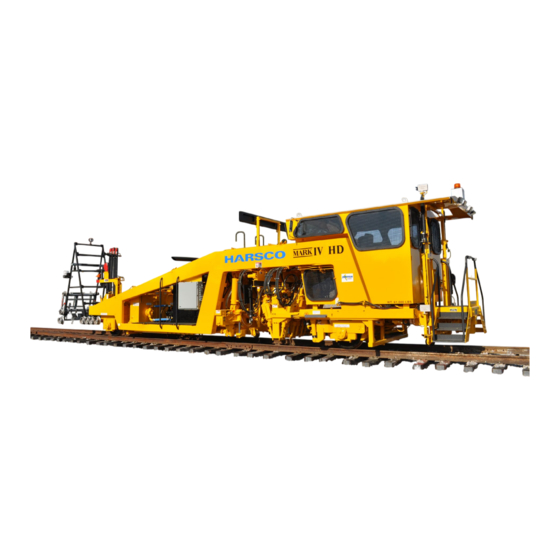
MARK IV HD J2 TAMPER SAFETY / GENERAL PAGE 1 - 13 BULLETIN 5082505 INFORMATION REVISED 10 - 2020 Identification FIGURE 1-1 FIGURE 1-2 MARK IV HD TAMPER LEFT SIDE MARK IV HD TAMPER RIGHT SIDE... -
Page 20: Serial Numbers
PAGE 1 - 14 SAFETY / GENERAL MARK IV HD J2 TAMPER REVISED 10 - 2020 INFORMATION BULLETIN 5082505 Serial Numbers 1.7.1 Serial Number - Machine Record the serial number and all other information from the serial number tag on the machine in the spaces provided in Figure 1-3. -
Page 21: Specifications
MARK IV HD J2 TAMPER SAFETY / GENERAL PAGE 1 - 15 BULLETIN 5082505 INFORMATION REVISED 10 - 2020 Specifications FIGURE 1-4 GENERAL SPECIFICATIONS... -
Page 22: General
PAGE 1 - 16 SAFETY / GENERAL MARK IV HD J2 TAMPER REVISED 10 - 2020 INFORMATION BULLETIN 5082505 Specifications 1.8.1 General - See Figure 1-4 Length - Basic Machine ....... .40.52 ft (12.35 m) -
Page 23: Engine
MARK IV HD J2 TAMPER SAFETY / GENERAL PAGE 1 - 17 BULLETIN 5082505 INFORMATION REVISED 10 - 2020 Specifications 1.8.4 Engine Cummins Model QSB 6.7 Tier IV ... 6 cylinder water cooled turbo charged diesel see engine manual for detailed information Horse Power. -
Page 24: Air System
PAGE 1 - 18 SAFETY / GENERAL MARK IV HD J2 TAMPER REVISED 10 - 2020 INFORMATION BULLETIN 5082505 Specifications 1.8.7 Air System Operating Pressures: Main System....... . . 100 -105 PSI (6.89 - 7.24 bar) -
Page 25: Tamping System
Optional ........ - Page 26 PAGE 1 - 20 SAFETY / GENERAL MARK IV HD J2 TAMPER REVISED 10 - 2020 INFORMATION BULLETIN 5082505 Notes: __________________________________________________________________________ __________________________________________________________________________ __________________________________________________________________________ __________________________________________________________________________ __________________________________________________________________________ __________________________________________________________________________ __________________________________________________________________________ __________________________________________________________________________ __________________________________________________________________________ __________________________________________________________________________ __________________________________________________________________________ __________________________________________________________________________ __________________________________________________________________________ __________________________________________________________________________ __________________________________________________________________________ __________________________________________________________________________ __________________________________________________________________________ __________________________________________________________________________ __________________________________________________________________________ __________________________________________________________________________...
- Page 27 SECTION 2 OPERATION...
- Page 28 THIS PAGE IS INTENTIONALLY BLANK...
- Page 29 MARK IV HD J2 TAMPER OPERATION PAGE 2 - 1 BULLETIN 5082505 REVISED 10 - 2020 SECTION 2 - OPERATION TABLE OF CONTENTS Operation - Controls ......... See Section 2.1 Operation - Jupiter II.
- Page 30 PAGE 2 - 2 OPERATION MARK IV HD J2 TAMPER REVISED 10 - 2020 BULLETIN 5082505 Notes: __________________________________________________________________________ __________________________________________________________________________ __________________________________________________________________________ __________________________________________________________________________ __________________________________________________________________________ __________________________________________________________________________ __________________________________________________________________________ __________________________________________________________________________ __________________________________________________________________________ __________________________________________________________________________ __________________________________________________________________________ __________________________________________________________________________ __________________________________________________________________________ __________________________________________________________________________ __________________________________________________________________________ __________________________________________________________________________ __________________________________________________________________________ __________________________________________________________________________ __________________________________________________________________________ __________________________________________________________________________ __________________________________________________________________________ __________________________________________________________________________ __________________________________________________________________________...
- Page 31 SECTION 2.1 OPERATION CONTROLS...
- Page 32 THIS PAGE IS INTENTIONALLY BLANK...
- Page 33 MARK IV HD J2 TAMPER OPERATION PAGE 2.1 - 1 BULLETIN 5082505 CONTROLS REVISED 10 - 2020 SECTION 2.1 - OPERATION CONTROLS TABLE OF CONTENTS 2.1.1 Controls / Locks Locations ........2.1 - 6 Travel Locks Locations .
-
Page 34: Section 2.1 - Operation
PAGE 2.1 - 2 OPERATION MARK IV HD J2 TAMPER REVISED 10 - 2020 CONTROLS BULLETIN 5082505 SECTION 2.1 - OPERATION CONTROLS TABLE OF CONTENTS Removable Vise Option ........2.1 - 24 Rear Platform Storage Compartments Option . - Page 35 MARK IV HD J2 TAMPER OPERATION PAGE 2.1 - 3 BULLETIN 5082505 CONTROLS REVISED 10 - 2020 SECTION 2.1 - OPERATION CONTROLS TABLE OF CONTENTS 2.1.8 Operator Armrest Controls - Left........2.1 - 38 Service Brake Lever .
- Page 36 PAGE 2.1 - 4 OPERATION MARK IV HD J2 TAMPER REVISED 10 - 2020 CONTROLS BULLETIN 5082505 SECTION 2.1 - OPERATION CONTROLS TABLE OF CONTENTS 2.1.11 Operator Keypad Controls - Right....... . .2.1 - 50 Information Key .
- Page 37 MARK IV HD J2 TAMPER OPERATION PAGE 2.1 - 5 BULLETIN 5082505 CONTROLS REVISED 10 - 2020 SECTION 2.1 - OPERATION CONTROLS TABLE OF CONTENTS 2.1.14 Callisto Geo System Option ........2.1 - 62 Callisto GPS Box .
-
Page 38: Controls / Locks Locations
2.1.1 Controls / Locks Locations Travel Locks Locations - See Figure 2.1-1 The MARK IV HD J2 Tamper has the following travel locks located in the general areas illustrated on the machine: (1) Workhead Lift - 1 Air Lock Pin Each Workhead - Controls In Cab... - Page 39 MARK IV HD J2 TAMPER OPERATION PAGE 2.1 - 7 BULLETIN 5082505 CONTROLS REVISED 10 - 2020 2.1.1 Controls / Locks Locations FIGURE 2.1-1 MARK IV HD TAMPER TRAVEL LOCKS...
- Page 40 BULLETIN 5082505 2.1.1 Controls / Locks Locations Controls Locations - See Figures 2.1-2 and 2.1-3 The MARK IV HD J2 Tamper has the following controls and components located in the general areas illustrated on the machine: (1) Engine (2) Air Cleaner...
- Page 41 MARK IV HD J2 TAMPER OPERATION PAGE 2.1 - 9 BULLETIN 5082505 CONTROLS REVISED 10 - 2020 2.1.1 Controls / Locks Locations FIGURE 2.1-2 FIGURE 2.1-3 MARK IV HD TAMPER - LEFT SIDE MARK IV HD TAMPER - RIGHT SIDE...
-
Page 42: Controls - Exterior
PAGE 2.1 - 10 OPERATION MARK IV HD J2 TAMPER REVISED 10 - 2020 CONTROLS BULLETIN 5082505 2.1.2 Controls - Exterior (1) Hand Rails - See Figure 2.1-4 (2) Steps - See Figure 2.1-4 (3) Platforms - See Figure 2.1-4... - Page 43 MARK IV HD J2 TAMPER OPERATION PAGE 2.1 - 11 BULLETIN 5082505 CONTROLS REVISED 10 - 2020 2.1.2 Controls - Exterior FIGURE 2.1-4 HAND RAILS - STEPS - PLATFORMS - COMPARTMENTS...
-
Page 44: Def Purge Cycle Indicator - Earlier Models Only
PAGE 2.1 - 12 OPERATION MARK IV HD J2 TAMPER REVISED 10 - 2020 CONTROLS BULLETIN 5082505 2.1.2 Controls - Exterior (7) Batteries - See Figure 2.1-5 The Batteries are located inside of the Battery Compartment on the left side of the machine. - Page 45 MARK IV HD J2 TAMPER OPERATION PAGE 2.1 - 13 BULLETIN 5082505 CONTROLS REVISED 10 - 2020 2.1.2 Controls - Exterior FIGURE 2.1-5 FIGURE 2.1-6 MASTER DISCONNECT SWITCH AIR DRAIN CABLE PURGE CYCLE INDICATOR - / COUPLER OPTION EARLIER MODELS ONLY...
- Page 46 PAGE 2.1 - 14 OPERATION MARK IV HD J2 TAMPER REVISED 10 - 2020 CONTROLS BULLETIN 5082505 2.1.2 Controls - Exterior (12) Remote Emergency Stop Switches Option - See Figure 2.1-7 The remote Emergency Stop Switches Option are located on the left and right sides of the machine.
-
Page 47: Fuel Tank Gauge
MARK IV HD J2 TAMPER OPERATION PAGE 2.1 - 15 BULLETIN 5082505 CONTROLS REVISED 10 - 2020 2.1.2 Controls - Exterior FIGURE 2.1-7 FIGURE 2.1-8 REMOTE EMERGENCY STOP SWITCH FUEL TANK GAUGE / AIR HORN SWITCH OPTION FIGURE 2.1-9 FIGURE 2.1-10... - Page 48 PAGE 2.1 - 16 OPERATION MARK IV HD J2 TAMPER REVISED 10 - 2020 CONTROLS BULLETIN 5082505 2.1.2 Controls - Exterior (19) Power Distribution Box (PDB) - See Figure 2.1-11 The Power Distribution Box (PDB) is located on the left side of the machine behind of the engine.
- Page 49 MARK IV HD J2 TAMPER OPERATION PAGE 2.1 - 17 BULLETIN 5082505 CONTROLS REVISED 10 - 2020 2.1.2 Controls - Exterior FIGURE 2.1-11 FIGURE 2.1-12 POWER DISTRIBUTION BOX EMERGENCY PUMP AND SWITCH FIGURE 2.1-13 FIGURE 2.1-14 SHADOWBOARD VALVES RECEIVER BUGGY VALVES...
-
Page 50: Buggy Lift Lock Pin
PAGE 2.1 - 18 OPERATION MARK IV HD J2 TAMPER REVISED 10 - 2020 CONTROLS BULLETIN 5082505 2.1.2 Controls - Exterior (26) Buggy Lift Lock Pin - See Figure 2.1-15 (27) Buggy Lift Valve - See Figure 2.1-16 (28) Buggy Lift Emergency Pump Switch - See Figure 2.1-16 (29) Buggy Lock Valves 1 - 2 - 3 - 4 - 5 - See Figure 2.1-16... -
Page 51: Video Camera Option
MARK IV HD J2 TAMPER OPERATION PAGE 2.1 - 19 BULLETIN 5082505 CONTROLS REVISED 10 - 2020 2.1.2 Controls - Exterior FIGURE 2.1-15 FIGURE 2.1-16 BUGGY LOCK PIN AND CABLE BUGGY CONTROL VALVES FIGURE 2.1-17 VIDEO CAMERA OPTION... -
Page 52: Engine Electronic Control Module (Ecm)
PAGE 2.1 - 20 OPERATION MARK IV HD J2 TAMPER REVISED 10 - 2020 CONTROLS BULLETIN 5082505 2.1.2 Controls - Exterior (32) Engine Electronic Control Module (ECM) - See Figure 2.1-18 (33) Engine Diagnostic Connector - See Figure 2.1-18 (34) Engine Diesel Exhaust Fluid (DEF) Doser Module - See Figure 2.1-18 The Engine Electronic Control Module (ECM), Diagnostic Connector and Diesel Exhaust Fluid (DEF) Doser Module are located inside of the engine enclosure on the right side of the engine. - Page 53 MARK IV HD J2 TAMPER OPERATION PAGE 2.1 - 21 BULLETIN 5082505 CONTROLS REVISED 10 - 2020 2.1.2 Controls - Exterior FIGURE 2.1-18 ENGINE ECM - DIAGNOSTIC CONNECTOR - DEF DOSER MODULE FIGURE 2.1-19 ENGINE COOLANT SUPPLY VALVES - BOOSTER PUMP...
- Page 54 PAGE 2.1 - 22 OPERATION MARK IV HD J2 TAMPER REVISED 10 - 2020 CONTROLS BULLETIN 5082505 2.1.2 Controls - Exterior (37) Emergency Towing Couplers Option - Being Towed - See Figure 2.1-20 (38) Emergency Towing Couplers Option - When Towing - See Figure 2.1-20 The Emergency Air Couplers are located on both the front and rear ends of the machine.
-
Page 55: Tow Bar Option
MARK IV HD J2 TAMPER OPERATION PAGE 2.1 - 23 BULLETIN 5082505 CONTROLS REVISED 10 - 2020 2.1.2 Controls - Exterior FIGURE 2.1-20 EMERGENCY TOWING COUPLERS OPTION - REAR FIGURE 2.1-21 TOW BAR OPTION... -
Page 56: Removable Vise Option
PAGE 2.1 - 24 OPERATION MARK IV HD J2 TAMPER REVISED 10 - 2020 CONTROLS BULLETIN 5082505 2.1.2 Controls - Exterior (40) Removable Vise Option - See Figure 2.1-22 The Removable Vise Option is located on the left front corner of the machine or on the rear of the machine. -
Page 57: Rear Platform Storage Compartments Option
MARK IV HD J2 TAMPER OPERATION PAGE 2.1 - 25 BULLETIN 5082505 CONTROLS REVISED 10 - 2020 2.1.2 Controls - Exterior FIGURE 2.1-23 REAR PLATFORM STORAGE COMPARTMENTS OPTION LEFT RIGHT FIGURE 2.1-24 LINING BAR / OIL STORAGE OPTION... -
Page 58: Cab Layout
PAGE 2.1 - 26 OPERATION MARK IV HD J2 TAMPER REVISED 10 - 2020 CONTROLS BULLETIN 5082505 2.1.3 Cab Layout - See Figure 2.1-25 When sitting in the operator’s seat inside of the Cab, the operator faces to the front of the machine. - Page 59 MARK IV HD J2 TAMPER OPERATION PAGE 2.1 - 27 BULLETIN 5082505 CONTROLS REVISED 10 - 2020 2.1.3 Cab Layout FIGURE 2.1-25 CAB LAYOUT...
-
Page 60: Ignition Switch
PAGE 2.1 - 28 OPERATION MARK IV HD J2 TAMPER REVISED 10 - 2020 CONTROLS BULLETIN 5082505 2.1.4 Control Panel - Left - See Figures 2.1-26 and 2.1-27 The Left Control Panel is located ahead of and to the left of the operator’s seat. The Left Control... -
Page 61: Engine Diagnostic Gauge
MARK IV HD J2 TAMPER OPERATION PAGE 2.1 - 29 BULLETIN 5082505 CONTROLS REVISED 10 - 2020 2.1.4 Control Panel - Left - See Figures 2.1-26 and 2.1-27 (2) Engine Diagnostic Gauge The gauge displays the engine operating information. See Appendix B - Miscellaneous - Diagnostic Gauge for operating information. -
Page 62: Work Light Switch
PAGE 2.1 - 30 OPERATION MARK IV HD J2 TAMPER REVISED 10 - 2020 CONTROLS BULLETIN 5082505 2.1.4 Control Panel - Left - See Figures 2.1-26 and 2.1-27 (4) Travel Light Switch - Forward (5) Travel Light Switch - Reverse Press the applicable switch to the IN position to turn ON the machine's forward or reverse travel lights. -
Page 63: Switch Plugs
MARK IV HD J2 TAMPER OPERATION PAGE 2.1 - 31 BULLETIN 5082505 CONTROLS REVISED 10 - 2020 2.1.4 Control Panel - Left - See Figures 2.1-26 and 2.1-27 (14) Switch Plugs When a switch position is not used, a switch plug is inserted into the empty position. -
Page 64: Control Panel - Center
PAGE 2.1 - 32 OPERATION MARK IV HD J2 TAMPER REVISED 10 - 2020 CONTROLS BULLETIN 5082505 2.1.5 Control Panel - Center - See Figure 2.1-28 The Center Control Panel is located directly ahead of the operator’s seat. The Center Control... - Page 65 MARK IV HD J2 TAMPER OPERATION PAGE 2.1 - 33 BULLETIN 5082505 CONTROLS REVISED 10 - 2020 2.1.5 Control Panel - Center FIGURE 2.1-28 CONTROL PANEL - CENTER RAIL AMBER...
-
Page 66: Panel Latch
PAGE 2.1 - 34 OPERATION MARK IV HD J2 TAMPER REVISED 10 - 2020 CONTROLS BULLETIN 5082505 2.1.6 Control Panel - Right - See Figures 2.1-29 and 2.1-30 The Right Control Panel is located ahead of and to the right of the operator’s seat. The Right... - Page 67 MARK IV HD J2 TAMPER OPERATION PAGE 2.1 - 35 BULLETIN 5082505 CONTROLS REVISED 10 - 2020 2.1.6 Control Panel - Right FIGURE 2.1-29 CONTROL PANEL - RIGHT FIGURE 2.1-30 POWER INVERTERS / SATELLITE RADIO...
-
Page 68: Operator Seat
PAGE 2.1 - 36 OPERATION MARK IV HD J2 TAMPER REVISED 10 - 2020 CONTROLS BULLETIN 5082505 2.1.7 Operator Seat - See Figure 2.1-31 The Operator’s Seat is located in the center of the cab. The Operator’s Seat consists of the... -
Page 69: Operator Armrest Controls - Left
MARK IV HD J2 TAMPER OPERATION PAGE 2.1 - 37 BULLETIN 5082505 CONTROLS REVISED 10 - 2020 2.1.7 Operator Seat - See Figure 2.1-31 (5) Operator Armrest Controls - Left The Left Armrest Controls are adjustable to suit the operator's preference. The armrest should be adjusted for operator comfort and easy access to all controls. - Page 70 PAGE 2.1 - 38 OPERATION MARK IV HD J2 TAMPER REVISED 10 - 2020 CONTROLS BULLETIN 5082505 2.1.8 Operator Armrest Controls - Left - See Figure 2.1-32 The Operator’s Left Armrest Controls are located on the left side of the Operator’s Seat. The Operator’s Left Armrest Controls consists of the following controls:...
-
Page 71: Operator Armrest Controls - Left
MARK IV HD J2 TAMPER OPERATION PAGE 2.1 - 39 BULLETIN 5082505 CONTROLS REVISED 10 - 2020 2.1.8 Operator Armrest Controls - Left FIGURE 2.1-32 OPERATOR LEFT ARMREST CONTROLS... -
Page 72: Combo Clamp Slew Switch - Left - Work Mode
PAGE 2.1 - 40 OPERATION MARK IV HD J2 TAMPER REVISED 10 - 2020 CONTROLS BULLETIN 5082505 2.1.8 Operator Armrest Controls - Left - See Figure 2.1-32 (4) Combo Clamp Slew Switch - Left - Work Mode When the switch is moved to the FORWARD position, the left side of the combo clamp frame will slew FORWARD and OUT. -
Page 73: Seat Height Switch
MARK IV HD J2 TAMPER OPERATION PAGE 2.1 - 41 BULLETIN 5082505 CONTROLS REVISED 10 - 2020 2.1.8 Operator Armrest Controls - Left - See Figure 2.1-32 (7) Seat Height Switch Rotate and hold the switch in the UPPER position to RAISE the operator’s seat. Rotate and hold the switch in the LOWER position to LOWER the operator’s seat. -
Page 74: Engine Rev Up Key
PAGE 2.1 - 42 OPERATION MARK IV HD J2 TAMPER REVISED 10 - 2020 CONTROLS BULLETIN 5082505 2.1.9 Operator Keypad Controls - Left - See Figure 2.1-33 The Operator’s Left Keypad Controls are located on the Operator’s Left Armrest. The Operator’s Left Keypad Controls consists of the following controls:... - Page 75 MARK IV HD J2 TAMPER OPERATION PAGE 2.1 - 43 BULLETIN 5082505 CONTROLS REVISED 10 - 2020 2.1.9 Operator Keypad Controls - Left FIGURE 2.1-33 OPERATOR LEFT KEYPAD CONTROLS Auto...
-
Page 76: Combo Clamp Lock Key - Work Mode
PAGE 2.1 - 44 OPERATION MARK IV HD J2 TAMPER REVISED 10 - 2020 CONTROLS BULLETIN 5082505 2.1.9 Operator Keypad Controls - Left - See Figure 2.1-33 (8) Combo Clamp Lock Key - Work Mode Press and release the key to UNLOCK the left and right combo clamp frame locks. Press and release the key again to LOCK the left and right combo clamp frame locks. -
Page 77: Workhead Lock Key
MARK IV HD J2 TAMPER OPERATION PAGE 2.1 - 45 BULLETIN 5082505 CONTROLS REVISED 10 - 2020 2.1.9 Operator Keypad Controls - Left - See Figure 2.1-33 (13) Workhead Lock Key - Work Mode Press and release the key to UNLOCK the left and right workhead locks. Press and release the key again to LOCK the left and right workhead locks. -
Page 78: Operator Armrest Controls - Right
PAGE 2.1 - 46 OPERATION MARK IV HD J2 TAMPER REVISED 10 - 2020 CONTROLS BULLETIN 5082505 2.1.10 Operator Armrest Controls - Right - See Figure 2.1-34 The Operator’s Right Armrest Controls are located on the right side of the Operator’s Seat. The Operator’s Right Armrest Controls consists of the following controls:... - Page 79 MARK IV HD J2 TAMPER OPERATION PAGE 2.1 - 47 BULLETIN 5082505 CONTROLS REVISED 10 - 2020 2.1.10 Operator Armrest Controls - Right FIGURE 2.1-34 OPERATOR RIGHT ARMREST CONTROLS...
-
Page 80: Combo Clamp Slew Switch - Right - Work Mode
PAGE 2.1 - 48 OPERATION MARK IV HD J2 TAMPER REVISED 10 - 2020 CONTROLS BULLETIN 5082505 2.1.10 Operator Armrest Controls - Right - See Figure 2.1-34 (4) Combo Clamp Slew Switch - Right - Work Mode When the switch is moved to the FORWARD position, the right side of the combo clamp frame will slew FORWARD and OUT. -
Page 81: Travel / Cycle Joystick - Work Mode
MARK IV HD J2 TAMPER OPERATION PAGE 2.1 - 49 BULLETIN 5082505 CONTROLS REVISED 10 - 2020 2.1.10 Operator Armrest Controls - Right - See Figure 2.1-34 (6) Travel / Cycle Joystick - Work Mode To propel the machine in the FORWARD direction, move the joystick to the FORWARD position and HOLD. - Page 82 PAGE 2.1 - 50 OPERATION MARK IV HD J2 TAMPER REVISED 10 - 2020 CONTROLS BULLETIN 5082505 2.1.11 Operator Keypad Controls - Right - See Figure 2.1-35 The Operator’s Right Keypad Controls are located on the Operator’s Right Armrest. The Operator’s Right Keypad Controls consists of the following group of keys:...
- Page 83 MARK IV HD J2 TAMPER OPERATION PAGE 2.1 - 51 BULLETIN 5082505 CONTROLS REVISED 10 - 2020 2.1.11 Operator Keypad Controls - Right FIGURE 2.1-35 OPERATOR RIGHT KEYPAD CONTROLS...
-
Page 84: Section 2.1 - Operation
PAGE 2.1 - 52 OPERATION MARK IV HD J2 TAMPER REVISED 10 - 2020 CONTROLS BULLETIN 5082505 2.1.11 Operator Keypad Controls - Right - See Figure 2.1-35 (B) Function Key Group - Outlined in MAGENTA (7) Enter (Accept) Key The Enter (Accept) Key functions in the same way as any Enter (Accept) Button that is currently displayed on the screen. -
Page 85: Arrow Up Key
MARK IV HD J2 TAMPER OPERATION PAGE 2.1 - 53 BULLETIN 5082505 CONTROLS REVISED 10 - 2020 2.1.11 Operator Keypad Controls - Right - See Figure 2.1-35 (C) Cursor Key Group - Outlined in GREEN The Cursor Keys are used for two different purposes. Normally these keys control manual adjustments to lift, line and super elevation. -
Page 86: Arrow Curved Left Key
PAGE 2.1 - 54 OPERATION MARK IV HD J2 TAMPER REVISED 10 - 2020 CONTROLS BULLETIN 5082505 2.1.11 Operator Keypad Controls - Right - See Figure 2.1-35 (C) Cursor Key Group - Outlined in GREEN (16) Arrow Curved Left Key... -
Page 87: Expanded Track View Key
MARK IV HD J2 TAMPER OPERATION PAGE 2.1 - 55 BULLETIN 5082505 CONTROLS REVISED 10 - 2020 2.1.11 Operator Keypad Controls - Right - See Figure 2.1-35 (D) Expanded Track View Key Group - Outlined in RED (18) Expanded Track View Key The track distance displayed on the normal view of the Work Screen is 150 feet ahead of the machine. - Page 88 PAGE 2.1 - 56 OPERATION MARK IV HD J2 TAMPER REVISED 10 - 2020 CONTROLS BULLETIN 5082505 2.1.12 Cab Air Conditioner / Pressurizer - See Figure 2.1-36 The Cab Air Conditioner / Pressurizer Controls are located on the top of the air conditioner / pressurizer unit in the right rear side of the cab wall.
-
Page 89: Cab Air Conditioner / Pressurizer Controls
MARK IV HD J2 TAMPER OPERATION PAGE 2.1 - 57 BULLETIN 5082505 CONTROLS REVISED 10 - 2020 2.1.12 Cab Air Conditioner / Pressurizer FIGURE 2.1-36 CAB AIR CONDITIONER / PRESSURIZER CONTROLS... - Page 90 The storage compartment can be used to store the Operator’s and Parts Manuals, personal safety equipment, tools, etc. An Operator's Manual must remain with the machine at all times. Additional or replacement manuals may be obtained by calling or writing Harsco Rail, Harsco Corporation.
-
Page 91: Storage Compartment
MARK IV HD J2 TAMPER OPERATION PAGE 2.1 - 59 BULLETIN 5082505 CONTROLS REVISED 10 - 2020 2.1.13 Miscellaneous Cab Controls FIGURE 2.1-37 FIGURE 2.1-38 MASTER CONTROL BOX TROUBLE LIGHT OPTION STORAGE COMPARTMENT / JUMP SEATS MCB / PDB POWER DISTRIBUTION BOX FIGURE 2.1-39... - Page 92 PAGE 2.1 - 60 OPERATION MARK IV HD J2 TAMPER REVISED 10 - 2020 CONTROLS BULLETIN 5082505 2.1.13 Miscellaneous Cab Controls (7) Cab Fans - See Figure 2.1-41 The Cab Fans are located in the left front upper and lower corners of the cab and next to rear cab door.
-
Page 93: Cab Fans
MARK IV HD J2 TAMPER OPERATION PAGE 2.1 - 61 BULLETIN 5082505 CONTROLS REVISED 10 - 2020 2.1.13 Miscellaneous Cab Controls FIGURE 2.1-41 FIGURE 2.1-42 CAB FANS CAB TOOL BOX OPTION FIGURE 2.1-43 FIGURE 2.1-44 PRINTER PRINTER VANDALISM COVER OPTION... - Page 94 PAGE 2.1 - 62 OPERATION MARK IV HD J2 TAMPER REVISED 10 - 2020 CONTROLS BULLETIN 5082505 2.1.14 Callisto Geo System Option - See Figures 2.1-45, 2.1-46 and 2.1-47 The Callisto Track Geometry system provides precise and accurate inertial based track geometry data for use with tampers.
- Page 95 MARK IV HD J2 TAMPER OPERATION PAGE 2.1 - 63 BULLETIN 5082505 CONTROLS REVISED 10 - 2020 2.1.14 Callisto Geo System Option FIGURE 2.1-45 CALLISTO GEO SYSTEM OPTION FIGURE 2.1-46 FIGURE 2.1-47 KEY SWITCH BOX LASER CUTOFF SWITCHES BOXES...
- Page 96 PAGE 2.1 - 64 OPERATION MARK IV HD J2 TAMPER REVISED 10 - 2020 CONTROLS BULLETIN 5082505 2.1.15 Diesel Fired Arctic Fox Heater Option - See Figure 2.1-48 The diesel fired Arctic Fox Heater Option is used to warm up the hydraulic fluid and engine coolant during cold weather operation.
- Page 97 MARK IV HD J2 TAMPER OPERATION PAGE 2.1 - 65 BULLETIN 5082505 CONTROLS REVISED 10 - 2020 2.1.15 Diesel Fired Arctic Fox Heater Option FIGURE 2.1-48 ARCTIC FOX HEATER OPTION ENGINE HEATER LEFT CONTROL PANEL...
- Page 98 PAGE 2.1 - 66 OPERATION MARK IV HD J2 TAMPER REVISED 10 - 2020 CONTROLS BULLETIN 5082505 2.1.16 Diesel Fired Cab Heater Option - See Figure 2.1-49 The Diesel Fired Cab Heater Option is used to provide additional cab heat during cold weather operation.
- Page 99 SECTION 2.2 OPERATION JUPITER II...
- Page 100 THIS PAGE IS INTENTIONALLY BLANK...
- Page 101 MARK IV HD J2 TAMPER OPERATION PAGE 2.2 - 1 BULLETIN 5082505 JUPITER II REVISED 10 - 2020 SECTION 2.2 - OPERATION JUPITER II TABLE OF CONTENTS 2.2.1 Jupiter II Control System........2.2 - 6 2.2.1.1...
- Page 102 PAGE 2.2 - 2 OPERATION MARK IV HD J2 TAMPER REVISED 10 -2020 JUPITER II BULLETIN 5082505 SECTION 2.2 - OPERATION JUPITER II TABLE OF CONTENTS 2.2.19 Toolbar Buttons Panel - Work Mode .......2.2 - 56 2.2.20...
- Page 103 MARK IV HD J2 TAMPER OPERATION PAGE 2.2 - 3 BULLETIN 5082505 JUPITER II REVISED 10 - 2020 SECTION 2.2 - OPERATION JUPITER II TABLE OF CONTENTS 2.2.23.2.4.8 High Density Digital Module Diagnostic Panel ....2.2 - 132 2.2.23.2.4.8.1...
- Page 104 PAGE 2.2 - 4 OPERATION MARK IV HD J2 TAMPER REVISED 10 -2020 JUPITER II BULLETIN 5082505 SECTION 2.2 - OPERATION JUPITER II TABLE OF CONTENTS 2.2.26 Expanded Track View Screen ........2.2 - 212 2.2.27...
- Page 105 MARK IV HD J2 TAMPER OPERATION PAGE 2.2 - 5 BULLETIN 5082505 JUPITER II REVISED 10 - 2020 SECTION 2.2 - OPERATION JUPITER II TABLE OF CONTENTS 2.2.36.5 F5 Defaults Table Button / Panel .......2.2 - 283 2.2.36.5.1...
-
Page 106: Jupiter Ii Control System
2.2.1 Jupiter II Control System 2.2.1.1 Jupiter System Introduction Jupiter II is the newest generation of Harsco Rail’s Jupiter Control System developed to meet the demanding computer control requirements of railway maintenance equipment. Jupiter II enhances the proven performance, ruggedness, reliability, speed, simplicity and diagnostic capability of the Jupiter Control System. -
Page 107: Simplified Electrical System
MARK IV HD J2 TAMPER OPERATION PAGE 2.2 - 7 BULLETIN 5082505 JUPITER II REVISED 10 - 2020 2.2.1 Jupiter II Control System 2.2.1.3 Simplified Electrical System The use of Jupiter II remote I/O devices helps simplify electrical systems through: Reduction of wires and wire terminations. -
Page 108: Jupiter System Network
PAGE 2.2 - 8 OPERATION MARK IV HD J2 TAMPER REVISED 10 -2020 JUPITER II BULLETIN 5082505 2.2.1 Jupiter II Control System 2.2.1.6 Jupiter System Network - See Figures 2.2-1 and 2.2-2 The Jupiter Control System is used to control most operating functions on the machine. -
Page 109: Jupiter System Description
MARK IV HD J2 TAMPER OPERATION PAGE 2.2 - 9 BULLETIN 5082505 JUPITER II REVISED 10 - 2020 2.2.1 Jupiter II Control System 2.2.1.7 Jupiter System Description The JAM contains a microprocessor that is responsible for distributing programming information to the other Jupiter modules on the machine. -
Page 110: Jupiter Diagnostics Overview
PAGE 2.2 - 10 OPERATION MARK IV HD J2 TAMPER REVISED 10 -2020 JUPITER II BULLETIN 5082505 2.2.1 Jupiter II Control System 2.2.1.8 Jupiter Diagnostics Overview The diagnostic screens incorporated into Jupiter II can be used to troubleshoot electrical systems and electrical components that are controlled or monitored by Jupiter. In some applications, not all components and systems on the machine can be checked or monitored by Jupiter. -
Page 111: Touch Screen Operation
MARK IV HD J2 TAMPER OPERATION PAGE 2.2 - 11 BULLETIN 5082505 JUPITER II REVISED 10 - 2020 2.2.1 Jupiter II Control System 2.2.1.10 Touch Screen Operation The machine is equipped with touch sensitive computer monitor screens. A Jupiter monitor is located in the cab of the machine ahead of the operator's seat. - Page 112 PAGE 2.2 - 12 OPERATION MARK IV HD J2 TAMPER REVISED 10 -2020 JUPITER II BULLETIN 5082505 2.2.1 Jupiter II Control System 2.2.1.10 Touch Screen Operation Some buttons will highlight yellow when they are pressed to turn on or enable the function. When the button is pressed again to turn off or disable the function, it will un-highlight gray.
- Page 113 MARK IV HD J2 TAMPER OPERATION PAGE 2.2 - 13 BULLETIN 5082505 JUPITER II REVISED 10 - 2020 2.2.1 Jupiter II Control System 2.2.1.11 Jupiter Program - See Figures 2.2-3 and 2.2-4 The Jupiter Program Information is displayed on the Alarm Panel of the Main Screen after a successful boot-up.
-
Page 114: Main Screens
PAGE 2.2 - 14 OPERATION MARK IV HD J2 TAMPER REVISED 10 -2020 JUPITER II BULLETIN 5082505 2.2.2 Main Screens 2.2.2.1 Travel Screen - See Figure 2.2-5 The Travel Screen is the initial screen that is displayed on the monitor after Jupiter boots- up and/or when operating in the Travel Mode. -
Page 115: Work Screen
MARK IV HD J2 TAMPER OPERATION PAGE 2.2 - 15 BULLETIN 5082505 JUPITER II REVISED 10 - 2020 2.2.2 Main Screens 2.2.2.2 Work Screen - See Figure 2.2-6 The Work Screen is the screen that is displayed on the monitor when operating in the Work Mode. -
Page 116: Expanded Track View Screen
PAGE 2.2 - 16 OPERATION MARK IV HD J2 TAMPER REVISED 10 -2020 JUPITER II BULLETIN 5082505 2.2.2 Main Screens 2.2.2.3 Expanded Track View Screen - See Figure 2.2-7 When operating in the Work Mode, press the Expanded Track View Key on the Right Operator Keypad or the F8 Key on the computer keyboard to display the Expanded Track View Screen. -
Page 117: Information Panel
MARK IV HD J2 TAMPER OPERATION PAGE 2.2 - 17 BULLETIN 5082505 JUPITER II REVISED 10 - 2020 2.2.3 Information Panel - See Figure 2.2-8 Press the Information Key on the Right Operator Keypad or the F6 Key on the computer keyboard to display the Information Panel on the screen. -
Page 118: Alarm Panel Navigation
PAGE 2.2 - 18 OPERATION MARK IV HD J2 TAMPER REVISED 10 -2020 JUPITER II BULLETIN 5082505 2.2.4 Alarm Panel Navigation FIGURE 2.2-9... -
Page 119: Alarm Panel
MARK IV HD J2 TAMPER OPERATION PAGE 2.2 - 19 BULLETIN 5082505 JUPITER II REVISED 10 - 2020 2.2.5 Alarm Panel - See Figures 2.2-10 The Alarm Panel displays the computer’s current time and date, and information and alarm messages. The panel displays the following: (1) Time and Date Panel: The panel displays the computers current time and date information. -
Page 120: Expanded Alarm Panel
PAGE 2.2 - 20 OPERATION MARK IV HD J2 TAMPER REVISED 10 -2020 JUPITER II BULLETIN 5082505 2.2.5 Alarm Panel 2.2.5.1 Expanded Alarm Panel - See Figure 2.2-11 (4) Page Down Button: Press the button to page the Text Panel down to view additional information and alarm messages that are longer than can be displayed on one screen. -
Page 121: Set Clock Panel
MARK IV HD J2 TAMPER OPERATION PAGE 2.2 - 21 BULLETIN 5082505 JUPITER II REVISED 10 - 2020 2.2.5 Alarm Panel 2.2.5.1.1 Set Clock Panel - See Figure 2.2-12 Press the Date and Time Panel on the Expanded Alarm Panel to display the Set Clock Panel on the screen. - Page 122 PAGE 2.2 - 22 OPERATION MARK IV HD J2 TAMPER REVISED 10 -2020 JUPITER II BULLETIN 5082505 2.2.6 Engine Status Panel - See Figures 2.2-13 and 2.2-14 The Engine Status Panel displays the following engine operating parameters: (1) Air System Pressure in PSI...
- Page 123 MARK IV HD J2 TAMPER OPERATION PAGE 2.2 - 23 BULLETIN 5082505 JUPITER II REVISED 10 - 2020 2.2.6 Engine Status Panel FIGURE 2.2-13 ENGINE STATUS PANEL A - B - C - D...
- Page 124 PAGE 2.2 - 24 OPERATION MARK IV HD J2 TAMPER REVISED 10 -2020 JUPITER II BULLETIN 5082505 2.2.6 Engine Status Panel - See Figures 2.2-13 and 2.2-14 (1) Air Pressure: 65 - 125 PSI (4.48 - 8.62 bar) (2) Battery Voltage: 23.6 - 29.0 VDC (3) Engine Coolant Temperature: 0 - 215°...
-
Page 125: Engine Status Panel
MARK IV HD J2 TAMPER OPERATION PAGE 2.2 - 25 BULLETIN 5082505 JUPITER II REVISED 10 - 2020 2.2.6 Engine Status Panel FIGURE 2.2-14 ENGINE STATUS PANEL A - B - C - D... -
Page 126: Mode Select Panel Navigation
PAGE 2.2 - 26 OPERATION MARK IV HD J2 TAMPER REVISED 10 -2020 JUPITER II BULLETIN 5082505 2.2.7 Mode Select Panel Navigation FIGURE 2.2-15... - Page 127 MARK IV HD J2 TAMPER OPERATION PAGE 2.2 - 27 BULLETIN 5082505 JUPITER II REVISED 10 - 2020 2.2.8 Mode Select Panel - See Figure 2.2-16 To switch from the Travel Mode to the Work Mode or vise-versa, press the Travel / Work Key on the Left Operator Keypad to display the Mode Select Panel on the screen.
- Page 128 PAGE 2.2 - 28 OPERATION MARK IV HD J2 TAMPER REVISED 10 -2020 JUPITER II BULLETIN 5082505 2.2.8 Mode Select Panel 2.2.8.1 F1 Travel Mode Button / Panel - See Figures 2.2-17 and 2.2-18 Press the F1 Travel Mode Button on the Mode Select Panel or the F1 Key on the Right Operator Keypad or computer keyboard to enable the Travel Mode and display the Travel Mode Panel on the screen.
-
Page 129: Mode Select Panel
MARK IV HD J2 TAMPER OPERATION PAGE 2.2 - 29 BULLETIN 5082505 JUPITER II REVISED 10 - 2020 2.2.8 Mode Select Panel 2.2.8.1 F1 Travel Mode Button / Panel FIGURE 2.2-17 FIGURE 2.2-18 TRAVEL MODE PANEL TRAVEL MODE PANEL 2.2.8.2... - Page 130 PAGE 2.2 - 30 OPERATION MARK IV HD J2 TAMPER REVISED 10 -2020 JUPITER II BULLETIN 5082505 2.2.8 Mode Select Panel 2.2.8.3 F3 Pump Control Pressure Button / Panel - See Figure 2.2-19 Press the F3 Pump Control Pressure Button on the Mode Select Panel or the F3 Key on the Right Operator Keypad or computer keyboard to display the Pump Control Pressure Panel on the screen.
-
Page 131: F3 Pump Control Pressure Button / Panel
MARK IV HD J2 TAMPER OPERATION PAGE 2.2 - 31 BULLETIN 5082505 JUPITER II REVISED 10 - 2020 2.2.8 Mode Select Panel 2.2.8.3 F3 Pump Control Pressure Button / Panel FIGURE 2.2-19 PUMP CONTROL PRESSURE PANEL... - Page 132 PAGE 2.2 - 32 OPERATION MARK IV HD J2 TAMPER REVISED 10 -2020 JUPITER II BULLETIN 5082505 2.2.8 Mode Select Panel 2.2.8.3.1 F1 Pump Pressure Calibration Button / Panel - See Figure 2.2-20 Press the F1 Pump Pressure Calibration Button on the F3 Pump Control Pressure Panel or the F1 Key on the Right Operator Keypad or computer keyboard to display the F1 Pump Pressure Calibration Panel on the screen.
-
Page 133: F1 Pump Pressure Calibration Button / Panel
MARK IV HD J2 TAMPER OPERATION PAGE 2.2 - 33 BULLETIN 5082505 JUPITER II REVISED 10 - 2020 2.2.8 Mode Select Panel 2.2.8.3.1 F1 Pump Pressure Calibration Button / Panel FIGURE 2.2-20 PUMP PRESSURE CALIBRATION PANEL... -
Page 134: F2 Pump Pressure Button
PAGE 2.2 - 34 OPERATION MARK IV HD J2 TAMPER REVISED 10 -2020 JUPITER II BULLETIN 5082505 2.2.8 Mode Select Panel 2.2.8.3.2 F2 Pump Pressure Button - See Figure 2.2-21 Press the F2 Pump Pressure Button (2) on the F3 Pump Control Pressure Panel or the F2 Key on the Right Operator Keypad or computer keyboard to adjust the pumps P1 - P2 proportional control valve hydraulic pressure. -
Page 135: F3 Pump Static Test Pressure Button
MARK IV HD J2 TAMPER OPERATION PAGE 2.2 - 35 BULLETIN 5082505 JUPITER II REVISED 10 - 2020 2.2.8 Mode Select Panel 2.2.8.3.3 F3 Pump Static Test Pressure Button - See Figure 2.2-22 Press the F3 Pump Static Test Pressure Button (3) on the F3 Pump Control Pressure Panel or the F3 Key on the Right Operator Keypad or computer keyboard to adjust the pumps P1 - P2 static hydraulic pressure. - Page 136 PAGE 2.2 - 36 OPERATION MARK IV HD J2 TAMPER REVISED 10 -2020 JUPITER II BULLETIN 5082505 2.2.9 Gear Select Panel - See Figure 2.2-23 When the Travel Mode is switched to Work Mode, or vise-versa, the Gear Select Panel is automatically displayed.
-
Page 137: Gear Select Panel
MARK IV HD J2 TAMPER OPERATION PAGE 2.2 - 37 BULLETIN 5082505 JUPITER II REVISED 10 - 2020 2.2.9 Gear Select Panel - See Figure 2.2-23 BOTH AXLES (5) F5 Gearbox Enable Button: Press the button or the F5 Key on the... - Page 138 PAGE 2.2 - 38 OPERATION MARK IV HD J2 TAMPER REVISED 10 -2020 JUPITER II BULLETIN 5082505 2.2.10 Machine Status Panel - See Figures 2.2-24 and 2.2-25 The Machine Status Panel on the Travel and Work Screens displays the following machine...
-
Page 139: Machine Status Panel
MARK IV HD J2 TAMPER OPERATION PAGE 2.2 - 39 BULLETIN 5082505 JUPITER II REVISED 10 - 2020 2.2.10 Machine Status Panel FIGURE 2.2-24 MACHINE STATUS PANEL FIGURE 2.2-25 MACHINE STATUS PANEL... - Page 140 PAGE 2.2 - 40 OPERATION MARK IV HD J2 TAMPER REVISED 10 -2020 JUPITER II BULLETIN 5082505 2.2.10 Machine Status Panel - See Figures 2.2-24 and 2.2-25 (6) Engine RPM Indicator: The slider will highlight yellow to display the actual engine RPM increases or decreases.
- Page 141 MARK IV HD J2 TAMPER OPERATION PAGE 2.2 - 41 BULLETIN 5082505 JUPITER II REVISED 10 - 2020 2.2.10 Machine Status Panel - See Figures 2.2-24 and 2.2-25 Important: The following indicators described are normally displayed on computer boot- up. The actual indicators that can displayed will be determined by which options are turned ON.
-
Page 142: Gearbox Shift Indicators
PAGE 2.2 - 42 OPERATION MARK IV HD J2 TAMPER REVISED 10 -2020 JUPITER II BULLETIN 5082505 2.2.11 Gearbox Shift Indicators The Gearbox Shift Indicators are located on the left side of the Machine Status Panel.The upper indicator is for the front axle and the lower indicator is for the rear axle. - Page 143 MARK IV HD J2 TAMPER OPERATION PAGE 2.2 - 43 BULLETIN 5082505 JUPITER II REVISED 10 - 2020 2.2.12 Distance Panel - See Figure 2.2-26 The Distance Panel on the Travel or Work Screens displays the following: See 2nd Toolbar Set - Work Mode - F1 Distance Menu Panel to set the distance and milepost values, and for operation information.
- Page 144 PAGE 2.2 - 44 OPERATION MARK IV HD J2 TAMPER REVISED 10 -2020 JUPITER II BULLETIN 5082505 2.2.13 Lift Panel - See Figures 2.2-27 and 2.2-28 The Lift Panel on the Work or Tie Finder Main Screens displays the following:...
- Page 145 MARK IV HD J2 TAMPER OPERATION PAGE 2.2 - 45 BULLETIN 5082505 JUPITER II REVISED 10 - 2020 2.2.13 Lift Panel FIGURE 2.2-27 FIGURE 2.2-28 LIFT PANEL LIFT PANEL...
-
Page 146: Superelevation / Crosslevel Panel
PAGE 2.2 - 46 OPERATION MARK IV HD J2 TAMPER REVISED 10 -2020 JUPITER II BULLETIN 5082505 2.2.14 Superelevation / Crosslevel Panel - See Figure 2.2-29 The Lift Panel on the Work or Tie Finder Option Screens displays the following:... - Page 147 MARK IV HD J2 TAMPER OPERATION PAGE 2.2 - 47 BULLETIN 5082505 JUPITER II REVISED 10 - 2020 2.2.14 Surface Graph Panel FIGURE 2.2-29 SUPERELEVATION / CROSSLEVEL PANEL...
- Page 148 PAGE 2.2 - 48 OPERATION MARK IV HD J2 TAMPER REVISED 10 -2020 JUPITER II BULLETIN 5082505 2.2.15 Surface Graph Panel - See Figure 2.2-30 The Surface Graph Panel on the Work or Tie Finder Screens displays the following: (1) Surface Graph...
- Page 149 MARK IV HD J2 TAMPER OPERATION PAGE 2.2 - 49 BULLETIN 5082505 JUPITER II REVISED 10 - 2020 2.2.15 Surface Graph Panel FIGURE 2.2-30 SURFACE GRAPH PANEL...
- Page 150 PAGE 2.2 - 50 OPERATION MARK IV HD J2 TAMPER REVISED 10 -2020 JUPITER II BULLETIN 5082505 2.2.16 Throws Graph Panel - See Figure 2.2-31 The Surface Graph Panel on the Work or Tie Finder Screens displays the following: (1) Surface Graph...
Need help?
Do you have a question about the MARK IV and is the answer not in the manual?
Questions and answers
If the wheel gauge on the MARK IV is measured at 56 5/8" and the track gauge is 56 1/2", would this be a problem?
Yes, a wheel gauge of 56 5/8 inches and a track gauge of 56 1/2 inches can be a problem for the Harsco MARK IV.
The track gauge of 56 1/2 inches is the standard gauge (4 feet 8.5 inches). If the wheel gauge is 56 5/8 inches, this means the distance between the inside edges of the wheels is 1/8 inch wider than the track gauge. This can lead to issues such as:
- Difficulty keeping the wheels properly aligned on the rails.
- Increased risk of derailment due to improper wheel-rail contact.
- Extra wear on the rail and wheel flanges.
For safe and efficient operation, the wheel gauge should match the track gauge within tight tolerances. A mismatch like this exceeds standard tolerances and should be corrected.
This answer is automatically generated
@Ken Belovarac 1/8th gauge difference ain't doing much at all, federal allowances up to class 4/5 (60-80mph) track is around 1" wide for an urgent defect and 1/2" narrow for an urgent. Not to mention if you find track with static 56 1/2" gauge on any track for more than 50' ill personally blow the roadmasters section crew. 56 1/2" is the standard you gauge the track to.