
Related Manuals for Dahua Technology DHI-IPMECD-105 Series


Summary of Contents for Dahua Technology DHI-IPMECD-105 Series
- Page 1 Boom Gate (DHI-IPMECD-105X Series) User’s Manual ZHEJIANG DAHUA VISION TECHNOLOGY CO., LTD. V1.0.0...
-
Page 2: Foreword
User’s Manual Foreword This manual introduces the installation, functions and operations of the boom gate. Read carefully before using the device, and keep the manual safe for future reference. Models Series Model DHI-IPMECD-1051-LM1515-T28 DHI-IPMECD-1051-LM1525-T30 DHI-IPMECD-1051-LM2525-T50 DHI-IPMECD-1051 Series DHI-IPMECD-1051-RM1515-T28 DHI-IPMECD-1051-RM1525-T30 DHI-IPMECD-1051-RM2525-T50 DHI-IPMECD-1052-LM30-T15 DHI-IPMECD-1052-LM3040-T28 DHI-IPMECD-1052-LM4050-T48... - Page 3 User’s Manual Signal Words Meaning Provides methods to help you solve a problem or save time. TIPS Provides additional information as a supplement to the text. NOTE Revision History Version Revision Content Release Time V1.0.0 First release. April 2023 About the Manual The manual is for reference only.
-
Page 4: Important Safeguards And Warnings
User’s Manual Important Safeguards and Warnings This section introduces content covering the proper handling of the boom gate, hazard prevention, and prevention of property damage. Read carefully before using the device, and comply with the guidelines when using it. Transportation Requirements Pack the boom gate with packaging materials provided by its manufacturer or materials with ... - Page 5 User’s Manual Installation Requirements WARNING Do not connect the boom gate to the power adapter when the adapter is powered on. Strictly comply with the local electrical safety codes and standards. Make sure that the ambient voltage is stable and meets the power supply requirements. Do not connect the boom gate to 2 or more kinds of power supplies, to avoid safety risks and ...
-
Page 6: Table Of Contents
User’s Manual Table of Contents Foreword ................................I Important Safeguards and Warnings ......................III 1 Product Overview ............................1 Product Introduction ................................1 Main Features ....................................1 2 Product Structure ............................2 Appearance ....................................2 Structure ......................................3 Casing Dimensions ..................................4 Product Dimensions .................................. -
Page 7: Product Overview
User’s Manual Product Overview Product Introduction The boom gate consists of a top cover, casing, transmission mechanism, control box, and boom. It can be controlled on the left or right side, and is ideal for access control at parking lots. 4 types of boom gates are available: the straight, telescopic, folding and fence boom gate. -
Page 8: Product Structure
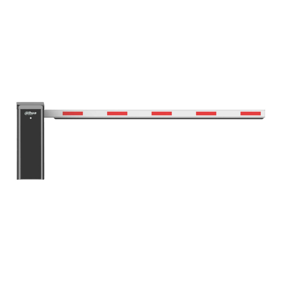
User’s Manual Product Structure Appearance Figure 2-1 Straight boom gate Figure 2-2 Telescopic boom gate Figure 2-3 Folding boom gate... -
Page 9: Structure
User’s Manual Figure 2-4 Fence boom gate Structure Figure 2-5 Structure Table 2-1 Structure description Description Description Boom handle Balance spring Spring adjustment screw Motor hand wheel Spring lock nut DC brushless servo motor Crank arm Boom... -
Page 10: Casing Dimensions
User’s Manual Casing Dimensions Figure 2-6 Casing dimensions (mm [inch]) Product Dimensions Straight boom gate (opens on the right, and the boom gate is installed on the left side of the roadway) - Page 11 User’s Manual Figure 2-7 Straight boom gate dimensions (mm [inch]) Telescopic boom gate (opens on the right, and the boom gate is installed on the left side of the roadway) Figure 2-8 Telescopic boom gate dimensions (mm [inch]) Folding boom gate (opens on the right, and the boom gate is installed on the left side of the ...
- Page 12 User’s Manual Figure 2-9 Folding boom gate dimensions (mm [inch]) Fence boom gate (opens on the right, and the boom gate is installed on the left side of the roadway) Figure 2-10 Fence boom gate dimensions (mm [inch])
-
Page 13: Direction
User’s Manual Direction You can recognize the direction of the boom gate by facing the door of its casing. Its direction is the side that the boom closes on. The diagrams are for reference only. Figure 2-11 Direction Opens on the right Opens on the left... -
Page 14: Product Installation
User’s Manual Product Installation Concrete Base Requirements This section introduces the requirements for selecting and constructing the concrete base. For details, see the corresponding construction guide. A concrete base is required for installing the boom gate. Pour concrete mixer into the location demarked for the base, to construct a concrete base that is between 150–250 mm above the ground. -
Page 15: Installing The Boom
User’s Manual Figure 3-2 Install the casing (mm [inch]) Table 3-1 Description Description Description Casing Plate Concrete Expansion screw (4-M12 × 160) Ground Concrete base Installing the Boom The installation diagrams in this section are for reference only. 3.3.1 Straight Boom Gate Step 1 Use 2 M12 ×... -
Page 16: Telescopic Boom Gate
User’s Manual Figure 3-3 Install the straight boom gate Table 3-2 Straight boom gate description Description Description M12 × 70 outer hexagon screw Handle connector Plate for boom handle — — 3.3.2 Telescopic Boom Gate The procedure for installing a telescopic boom gate is the same as that of installing the straight boom gate. -
Page 17: Fence Boom Gate
User’s Manual Figure 3-4 Install the folding boom gate Table 3-3 Folding boom gate description Description Description Support plate Stainless steel tube Cast aluminum casing Bearing 3.3.4 Fence Boom Gate Step 1 Follow Step 1–Step 3 in "3.3.1 Straight Boom Gate". Step 2 Use the hex socket to fix one end of the bearing of the U-shaped connector to the cone shaft of the casing. -
Page 18: Connecting Cables
User’s Manual Figure 3-5 Install the fence boom gate Table 3-4 Fence boom gate description Description Description Lower horizontal bar Cone shaft U-shaped connector — — Connecting Cables The wiring for the boom gate was completed before delivery. Simply connect the boom gate to the power supply and protective earth wire for it to begin working. -
Page 19: Connecting Controller Ports
User’s Manual 3.4.1 Connecting Controller Ports Figure 3-6 Wiring diagram of the controller... - Page 20 User’s Manual Table 3-5 Controller port description Description Description Fuse. 24 VDC power input. RS-485 communication interface. Connects to the RS-485 port of the access control camera through a twisted pair cable, so that the Bluetooth mode interface (optional). camera can obtain the working status, fault code and log of the boom gate.
-
Page 21: Configuring Controller Parameters
User’s Manual Description Description Function buttons. The 4 function buttons have 2 working statuses: the normal working status and menu setting status. In the normal working status, Digital tube display. Displays the working you can press Open, Close, or status, parameters, menu items, and other Stop to open, close, or stop the information of the boom gate. - Page 22 User’s Manual Table 3-6 Common menu list Menu Function Default Range Description The higher the value, the faster the boom gate F-00 Opening speed 15–100 opens. The higher the value, the faster the boom gate F-01 Closing speed 15–100 closes. Opening The angle that the boom gate starts F-02...
- Page 23 User’s Manual The angle that the boom gate starts closing when the speed is slow. When it is closing and reaches this angle, the boom gate will close at the F-07 closing speed until the boom gate is completely closed. This function is invalid if F-05 is set to 0, or is greater than the F-03 closing deceleration angle.
- Page 24 User’s Manual After entering the menu, set the speed for learning the up limit first. The LED displays "1-XX" (XX refers to the speed for learning the up limit). You can press the Open and Close buttons to adjust the speed. After setting the speed for learning the up limit, press Settings, and the LED displays "2-XX"...
- Page 25 User’s Manual Menu Function Default Range Description RS-485 communication 0: 115200, 1: 38400, 2: 19200, 3: 9600. H-25 0–3 baud rate. Leave it as the default. RS-485 communication H-26 1–255 — address. Enter the fleet mode H-31 when opening the boom 0, 1 See Advanced Settings Details.
- Page 26 User’s Manual Select one of the options, and then press Settings, the parameters of F-00 to F-07 are automatically modified, and H-33 is automatically changed to 1. If the speed does not meet the on-site requirements, you can fine-tune the parameters of F-00 to F-07. This option can reduce the difficulty of on-site commissioning and reduce the commissioning time.
- Page 27 User’s Manual camera sends closing signal. The boom gate does not enter the fleet mode when it opens after receiving opening command from the connected camera. Set H-31 to 0, and when the boom gate is opened, press and hold Open on the remote ...
- Page 28 User’s Manual You can use H-34, configure F-08 and F-09 to adjust the vertical and horizontal positions, but using H-34 is more intuitive. H-35 adjust the up limit manually (recommended for straight boom gate or fence boom gate, with boom length of 5 meters or more) After entering the H-35 command, the LED shows L-00, and then the boom rises.
- Page 29 User’s Manual the down limit has been found. At this moment, the gate stops, and you need to manually find the vertical and horizontal positions of the boom: Press and hold Open, the boom works in the opening direction, until it is in the required horizontal position.
-
Page 30: Adjusting Spring Balance
User’s Manual Error Code Reason Er. 7 Alarm when someone rises the boom manually. 3.4.2.4 LED Message Display Table 3-10 LED message display Message Description The plug of the motor sensor is not inserted or the motor sensor fails, which might be IdLE caused by loosen cable. - Page 31 User’s Manual Boom Type Boom Length L (m) Spring Cable Diameter (mm) Remarks Straight Boom with yellow L < 3 Φ4.5 Rubber Strip Telescopic Boom 3–4 Φ4.5 + Φ4.5 Telescopic Boom 4–5 Φ4.5 + Φ5.5 Telescopic Boom 5–6 Φ4.5 + Φ6 Folding Boom 5 ≥...
-
Page 32: Remote Control
User’s Manual Description Description Spring adjustment nut Hook M12 lock nut Spring lock nut M10 screw Spring adjustment screw (M8 × 140 mm) Step 3 Adjust the spring. Power off the boom gate. Rotate the motor hand wheel to make the boom move in the direction of closing the boom gate. - Page 33 User’s Manual Unpairing Step 1 Unplug the remote control receiver (or power off the boom gate). Step 2 Press and hold the Close button of the paired remote control, and then plug in the remote control receiver (or power on the boom gate). Step 3 When the indicator flashes quickly, the remote control enters the unpairing status.
-
Page 34: Maintenance
User’s Manual Maintenance Clean the casing surface to avoid dust and litter. Check the fasteners are well tightened once a month, and fasten them when necessary. Check spring balance after the boom gate runs every 300,000 times; replace the spring with a ... -
Page 35: Appendix 1 Faq
User’s Manual Appendix 1 1. Power on the boom gate, open or close it by remote control. The boom does not work. Check whether the controller power indicator is on. If not, check whether the fuse is in good condition. Check whether the remote control matches with the boom gate, or the battery is low. - Page 36 User’s Manual 11. The remote control failed to learn. The remote control does not match the receiver. Contact the manufacturer to confirm whether it is the matched remote control. 12. The boom is not vertical after the boom opens. Check whether the vertical position value of the controller is properly configured. If H-33 is set to 0, adjust the F-08 value of the controller.
-
Page 37: Appendix 2 Cybersecurity Recommendations
User’s Manual Appendix 2 Cybersecurity Recommendations Cybersecurity is more than just a buzzword: it’s something that pertains to every device that is connected to the internet. IP video surveillance is not immune to cyber risks, but taking basic steps toward protecting and strengthening networks and networked appliances will make them less susceptible to attacks. - Page 38 User’s Manual between 1024–65535, reducing the risk of outsiders being able to guess which ports you are using. HTTPS We suggest you to enable HTTPS, so that you visit Web service through a secure communication channel. MAC Address Binding We recommend you to bind the IP and MAC address of the gateway to the device, thus reducing the risk of ARP spoofing.
- Page 39 User’s Manual Enable IP/MAC address filtering function to limit the range of hosts allowed to access the device. More information Please visit Dahua official website security emergency response center for security announcements and the latest security recommendations.
- Page 40 User’s Manual...
Need help?
Do you have a question about the DHI-IPMECD-105 Series and is the answer not in the manual?
Questions and answers