
Related Manuals for Siemens A Series


Summary of Contents for Siemens A Series
- Page 1 A-Series 530 lb-in Actuator Installation, Operation and Maintenance Manual A6V12069989 Siemens Industry, Inc. 09/26/2023...
-
Page 2: Table Of Contents
Table of Contents Introduction ........................3 Safety ..........................3 Heater ..........................4 Principle of Operation ..................... 4 Electrical Operation ......................4 Mechanical Operation ..................... 5 Calibration Sequence ..................... 5 Storage .......................... 6 Actuation ........................7 Manual Operation ......................7 Remote Operation ......................8 A-Series 530 lb-in 120V On/Off Actuator with Interposing Relay Board (Servo IRB) .. -
Page 3: Introduction
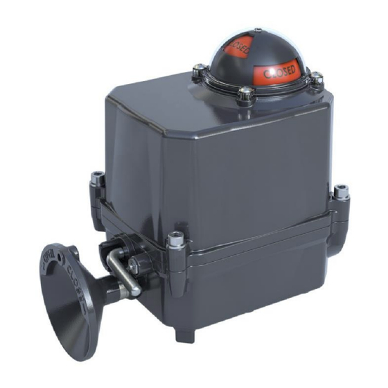
The A-Series 530 lb-in actuator is a quarter-turn industrial electric actuator. It features a compact, reliable design that mounts directly to Siemens resilient seat butterfly valves without the need for brackets and linkages. This unit provides up to 530 lb-in (60 Nm) torque, and is available in 24V and 120V, Two-Position (On/Off) and Modulating units all in NEMA 4X and IP65-rated housings. -
Page 4: Heater
Introduction Heater Heater The A-Series 530 lb-in actuator includes a factory-installed heater that prevents condensation from forming inside the actuator. Units with On/Off actuation use a Positive Temperature Coefficient (PTC) style heater which has a unique temperature – resistance characteristic. The heater self-regulates by increasing its electrical resistance relative to is temperature. -
Page 5: Mechanical Operation
Introduction Mechanical Operation Mechanical Operation Mechanically, the ratio of the gearing determines the output speed of the unit. The actuator utilizes high efficiency spur gears. Positioning is determined by an indicator/cam shaft, which is linked to the output shaft. In the declutched position, the manual override drives the output. -
Page 6: Storage
Storage CAUTION Actuators are not weatherproof unless they are properly installed on the valve or prepared for storage. Siemens cannot accept responsibility for deterioration caused on-site. ● Store units on a shelf or wooden pallet to protect against floor dampness. -
Page 7: Actuation
Actuation Manual Operation Actuation Manual Operation The A-Series 530 lb-in actuators have a declutchable, manual override system. To manually operate the actuators, push in the manual override button and rotate the declutchable lever counter-clockwise until it reaches the 12 o’clock position. Once the declutchable lever is in position, turn the handwheel until the valve reaches the required position. -
Page 8: Remote Operation
Actuation Remote Operation Remote Operation CAUTION ● Verify that the main electric power supplied to the actuator is in compliance with the specifications on the actuator label. ● Engaging the handwheel before or during the application of a supply voltage will prevent the actuator motor from operating. -
Page 9: A-Series 530 Lb-In 120V Modulating Actuator With Servo Controller
Actuation A-Series 530 lb-in 120V Modulating Actuator with Servo Controller 120V On/Off with 1 set AUX Switches MODEL – A226.530 Fig. 2: Model A226.530 Wiring Fig. 3: Model A226.530 Servo Controller. A-Series 530 lb-in 120V Modulating Actuator with Servo Controller Power connection that energizes the Servo controller and powers the actuator under control. -
Page 10: A-Series 530 Lb-In 24V On/Off Servo Controller
Actuation A-Series 530 lb-in 24V On/Off Servo Controller Servo controller electronics package. The control signal may be applied locally from a hand-held signal generator or remotely from a process controller. In the case of an over torque fault, the electronics are configured to limit max current, which will effectively lock the rotor. -
Page 11: A-Series 530 Lb-In 24V Modulating Actuator With Servo Controller
Actuation A-Series 530 lb-in 24V Modulating Actuator with Servo Controller 24V On/Off with 1 Set AUX Switches Model – A126.530 Fig. 5: Model A126.530 Wiring Fig. 6: Model A126.530 Servo Controller. A-Series 530 lb-in 24V Modulating Actuator with Servo Controller To control the actuator remotely from a process controller in a modulating application, you must apply the proper supply voltage and the configured control signal to the Servo controller electronics package. - Page 12 Actuation A-Series 530 lb-in 24V Modulating Actuator with Servo Controller 24V Modulating with 1 Set AUX Switches Model – A166.530 Fig. 7: Model A166.530 Wiring. 12 | 31 09/26/2023 A6V12069989...
-
Page 13: Mounting The Actuator
Mounting the Actuator Mounting the Actuator All A-Series electric actuators are suitable for direct mounting on Siemens resilient seat butterfly valves. With proper mounting hardware, the A-Series actuator can be installed onto other quarter-turn valves or devices. NOTICE ● The standard mounting position for the actuator orients the unit with its handwheel in a vertical plane and parallel to the pipeline. -
Page 14: Commissioning
Commissioning Wiring the Actuator Commissioning Wiring the Actuator WARNING Turn off all power and lockout/tag out service panel before installing or modifying any electrical wiring. 1. Remove the actuator cover. Keep the cover on hand for reference. 2. Wire the actuator according to the wiring diagram attached to the inside of the actuator cover. -
Page 15: Maintenance
Commissioning Maintenance Standard factory setting of the travel limit switches allows 90° travel between open and closed positions. Cams for each switch are adjustable for applications where less than 90-degree travel is desired between the open and closed positions. 1. Manually operate the actuator to the closed position. 2. -
Page 16: A-Series 530 Lb-In Servo Controller
A-Series 530 lb-in Servo Controller Safety A-Series 530 lb-in Servo Controller Safety Hazard-Free Use This device left the factory in proper condition to be safely installed and operated in a hazard-free manner. The notes and warnings in this document must be observed by the user to ensure hazard-free operation of this device. -
Page 17: Quick Start Guide
A-Series 530 lb-in Servo Controller Quick Start Guide Quick Start Guide WARNING 1. Turn off all power and lockout/tag out service panel before installing or modifying any electrical wiring. 2. The butterfly valve disc should not be manually rotated until the valve is fully installed in the piping. -
Page 18: Description Of Operation
A-Series 530 lb-in Servo Controller Description of Operation Description of Operation The Servo controller provides complete modulating control and monitoring of the 530 lb-in Electric Actuator. The basic function of the Servo is to position the Actuator in response to a command signal from a process controller. The process controller contains a desired process setpoint entered by the user, and continually monitors the process variable (such as flow rate, tank level, etc.) through some type of sensor. -
Page 19: Configurable Settings
A-Series 530 lb-in Servo Controller User Interface Feature Setting Configurable Dead Band Control Heater Setpoint 122°F (50°C) Table 1: Servo Controller Default Settings Configurable Settings Settings can be changed locally by utilizing the push-button associated with each product setting. Each push-button is labeled and placed below a set of LEDs, with individual labels corresponding to the setting. - Page 20 A-Series 530 lb-in Servo Controller User Interface Input Setting Description 0 to 5V Analog Voltage Range Minimum: 0V Maximum: 5V 2 to 10V Analog Voltage Range Minimum: 1.5V Maximum: 12V Table 2: Servo Input Settings Output Signal Type - Configurable Output signals report the position of the valve under control, based on the magnitude of the signal.
-
Page 21: Operating Modes
Autocalibration Mode Autocalibration mode is entered by pressing and holding the Autocalibration (Cal) button for at least 1 second. Entering Autocalibration mode starts the Autocalibration sequence: a series of commands performed by the Servo controller on the actuator to A6V12069989 09/26/2023... -
Page 22: Status Indication
A-Series 530 lb-in Servo Controller User Interface determine the operating points. During the Autocalibration sequence, the Servo should be monitored to ensure it operates correctly. The calibration LED will flash slowly to show that Autocalibration has been entered and will continue to flash at the end of travel until Autocalibration completes. - Page 23 A-Series 530 lb-in Servo Controller User Interface OPEN (Green LED) CLOSE (Red LED) Description of Activity ON (solid) ON (flashing) At fully open position, moving in the closed direction. ON (flashing) Moving in the closed direction. ON (solid) Stopped at full closed position. ON (flashing) ON (solid) At full closed position, moving in the...
-
Page 24: Hardware Description
A-Series 530 lb-in Servo Controller Hardware Description Calibration The calibration (CAL STATUS) LED indicator, located at the bottom right, serves as a calibration status indicator for the Servo Controller. Calibration (CAL STATUS) LED Description Autocalibration routine previously completed successfully. ON (slowly flashing) Servo operating using default factory calibration settings. - Page 25 A-Series 530 lb-in Servo Controller Hardware Description Voltage Field Terminals Internal Connections High voltage (> 15V) Power (Live, Neutral) Motor Terminals Heater Header Low voltage (< 15V) Input Signal FB Pot Header (Input+, Input-), Limit Switch Header Output Signal (Output+, Output-) Voltage Free Auxiliary Switch Auxiliary Switch Header...
- Page 26 A-Series 530 lb-in Servo Controller Hardware Description Fig. 14: 120V Servo Wiring Input Signal - Required Connection Connection for the input signal that positions the valve under control, based on the magnitude of the signal. The signal that is present at this connection should be based on the input setting (see Product Settings).
- Page 27 A-Series 530 lb-in Servo Controller Hardware Description Limit Switch Header - Required Connection Connections for the travel limit switches, which indicate to the Servo controller when an end of travel setpoint has been reached. The Servo provides a logic level voltage at the Open and Close terminals of this connection.
-
Page 28: Troubleshooting
A-Series 530 lb-in Servo Controller Troubleshooting Troubleshooting WARNING Turn off all power and lockout/tag out service panel before installing or modifying any electrical wiring. See the actuator manual before adjusting or replacing any actuator components. Check for any active faults before testing or acting on any issues. Resolving Issues Issue Possible Causes... -
Page 29: Clearing Fault Conditions
A-Series 530 lb-in Servo Controller Troubleshooting Clearing Fault Conditions Fault Condition Possible Causes Possible Solutions Command Signal Fault Command signal does not Adjust the Input setting to match input setting match the command signal used. The Servo is Incorrectly Verify wire connections wired against the wiring diagram. - Page 30 A-Series 530 lb-in Servo Controller Troubleshooting 6. Hold the screwdriver in place and ensure that any slip in the gear does not turn the fault LED back on. – If the fault activates, adjust the potentiometer slightly more. 7. Tighten the potentiometer gear setscrew. 8.
- Page 31 Issued by Siemens Industry, Inc. Smart Infrastructure 1000 Deerfield Pkwy Buffalo Grove IL 60089 +1 847-215-1000 © Siemens, 2023 Technical specifications and availability subject to change without notice. A6V12069989...
Need help?
Do you have a question about the A Series and is the answer not in the manual?
Questions and answers