Table of Contents
Advertisement
Quick Links
K1EL
Features
• 3.8MHz Amateur Phone Band Receiver
• 100 KHz Tuning Range
• Wideband Hi-Fi AM mode reception
• Single Sideband mode with on board BFO
• Uses single chip TRF TA7642 IC
• Low impedance 8 ohm speaker output
• Main tuning with separate Bandspread
• RF Gain and AF Gain controls
• 9-12 VDC operation
• Varactor Diode tuning
• NE602 1
st
Mixer
• 455 KHz IF with ceramic filter
• TDA7052 audio amplifier IC
• On board 6 volt regulator
AM75 Datasheet – A.3
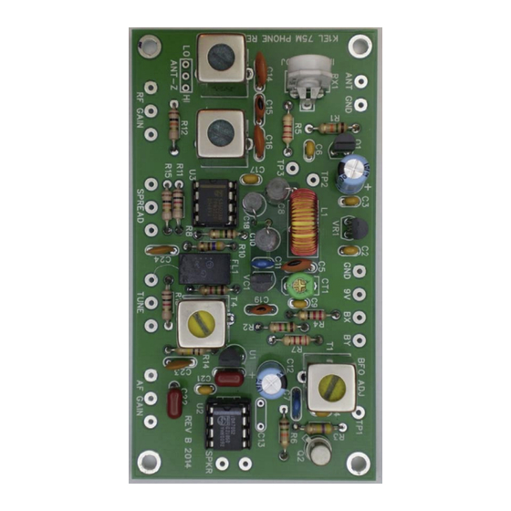
75 Meter AM Phone Receiver
Figure 1 – Assembled AMR75 Board
6/1/2017
Description
The AMR75 is an experimental AM phone
band receiver which makes use of a TDA7642
TRF receiver IC along with a conventional
NE602 first mixer stage. The design provides
a wide bandwidth Hi-Fi output which is
suitable for listening to the AM groups that are
popular on 75 meters. The radio was designed
as a nostalgic callback to vacuum tube
receivers of the 1950s with main tuning, band
spread, 455 KHz IF, BFO, and plenty of audio
output. This radio is called experimental since
the builder may want to tailor the radio's
performance by adjusting component values.
Also the builder needs to supply a suitable
enclosure or open chassis platform.
AMR75
Page 1
Advertisement
Table of Contents

Related Manuals for K1EL AMR75

Summary of Contents for K1EL AMR75
- Page 1 75 Meter AM Phone Receiver Features Description • 3.8MHz Amateur Phone Band Receiver The AMR75 is an experimental AM phone • 100 KHz Tuning Range band receiver which makes use of a TDA7642 • Wideband Hi-Fi AM mode reception TRF receiver IC along with a conventional NE602 first mixer stage.
- Page 2 75 Meter AM Phone Receiver K1EL AMR75 Theory of Operation This discussion will refer to the block diagram on page 3 and the schematics on page 4. We will start at the antenna input with a two stage input bandpass filter consisting of two 10.7 MHZ 42IF123 IF transformers that have been padded to resonate on the 75 meter band.
- Page 3 75 Meter AM Phone Receiver K1EL AMR75 Block Diagram Figure 2 – Assembled AMR75 Block Diagram AM75 Datasheet – A.3 6/1/2017 Page 3...
- Page 4 75 Meter AM Phone Receiver K1EL AMR75 AMR75 Schematics AM75 Datasheet – A.3 6/1/2017 Page 4...
- Page 5 75 Meter AM Phone Receiver K1EL AMR75 AMR75 Kit Parts List 100K Brown Black Yellow R12, R15 Brown Black Orange R2, R9 1.5K Brown Green Red R1, R6 Brown Green Orange R11, R13 Brown Black Red Brown Black Green 4.7K Yellow Violet Red 2.2K...
- Page 6 75 Meter AM Phone Receiver K1EL AMR75 PCB Assembly Install and test the 6 volt power supply Install C2, VR1, C1 and C3. Observe polarity for C1, long lead goes in square hole. Attach power leads to the 9V and GND pads and attach them to a suitable power supply. 9V is optimal but any voltage from 8V to 12V will work.
- Page 7 Route this wire so that it runs close to, but does not touch, the AMR75 board. Apply power up the AMR75 and adjust the CT1 trimmer so that you hear a zero beat on the receiver. Use a plastic screwdriver for best results. A small metal jeweler’s screwdriver can work but note the screwdriver will influence the frequency and it might take several trials to get the frequency correct.
- Page 8 AM75. We will follow the same procedure outlined above with the exception that we will be listening for a signal from the AMR75 as we adjust CT1. Make sure you have turned the RF gain control fully clockwise and the AF gain to mid-position.
- Page 9 75 Meter AM Phone Receiver K1EL AMR75 General Operational Notes This receiver has a surplus of gain. This will become apparent when band conditions are good. You will find that you rarely have to turn the RF gain control all the way up, particularly for SSB stations. If you are finding that signals are distorted, try backing off on the RF gain control.
- Page 10 75 Meter AM Phone Receiver K1EL AMR75 Close Up Photos of an Assembled AMR75 PC Board AM75 Datasheet – A.3 6/1/2017 Page 10...
- Page 11 75 Meter AM Phone Receiver K1EL AMR75 AM75 Datasheet – A.3 6/1/2017 Page 11...
- Page 12 75 Meter AM Phone Receiver K1EL AMR75 Figure 3 – Assembled AMR75 Board Close Up AM75 Datasheet – A.3 6/1/2017 Page 12...
- Page 13 75 Meter AM Phone Receiver K1EL AMR75 Figure 4 – Printed Circuit Board Image AM75 Datasheet – A.3 6/1/2017 Page 13...
- Page 14 AMR75 Contact Information The AMR75 Kit is fully guaranteed; if you are not satisfied please return the kit for a full refund. Questions will be handled by e-mail via: k1el.kitsinfo@gmail.com Watch the Hamcrafters Website for latest updates and new product offerings: http://www.hamcrafters.com...
-
Page 15: Appendix A - Kit Construction Hints
75 Meter AM Phone Receiver K1EL AMR75 Appendix A - Kit Construction Hints 1. Find a good workspace. It is essential that you have a good place to work on your kit, You will need room to spread out your parts and have access to tools. Good lighting and ventilation is essential. -
Page 16: Appendix C - Soldering Basics
75 Meter AM Phone Receiver K1EL AMR75 When building your kit please remember that Soldering Irons and Solder are used at High Temperatures! Soldering Irons can remain hot for many minutes after being turned off. Never touch the tip to see if it is hot. - Page 17 75 Meter AM Phone Receiver K1EL AMR75 5. Remove the solder and then remove the iron: Fig C3 - Remove the solder 6. Allow the joint to cool and visually inspect for defects or other problems. You should have a solder joint with a bright shiny finish and a profile like that shown in Fig.
- Page 26 TA7642 LINEAR INTEGRATED CIRCUIT The TA7642 is suitable for low voltage portable Radio, cassette system and other wireless AM system. The package of UTC7642 is TO-92. *Low operating voltage: Down to V =1.3V *Low Quiescent Current:I =0.2mA *Low external component required. TO-92 23pF 12pF...
- Page 27 TA7642 LINEAR INTEGRATED CIRCUIT (Tested at Ta=25°C,V =1.3V,fm=1kHz,f =1MHz,MOD=30%,unless other specified) Supply Voltage Quiescent Current 0.14 0.20 0.30 MΩ Input Resistance µV Maximum sensitivity =3mV Detector Output Voltage =10mV ∆A The Range of AGC RAGC 100k 1.5k 0.01 F TA7642 Vout 0.1 F 100k...
-
Page 28: Integrated Circuits
INTEGRATED CIRCUITS DATA SHEET TDA7052 1 W BTL mono audio amplifier July 1994 Product specification File under Integrated Circuits, IC01... -
Page 29: General Description
Philips Semiconductors Product specification 1 W BTL mono audio amplifier TDA7052 GENERAL DESCRIPTION The TDA7052 is a mono output amplifier in a 8-lead dual-in-line (DIL) plastic package. The device is designed for battery-fed portable audio applications. Features: • No external components •... - Page 30 Philips Semiconductors Product specification 1 W BTL mono audio amplifier TDA7052 Fig.1 Block diagram. PINNING supply voltage OUT1 output1 input GND2 ground (substrate) GND1 ground (signal) n.c. not connected n.c. not connected OUT2 output2 July 1994...
- Page 31 Philips Semiconductors Product specification 1 W BTL mono audio amplifier TDA7052 FUNCTIONAL DESCRIPTION The TDA7052 is a mono output amplifier designed for battery-fed portable audio applications, such as tape recorders and radios. The gain is fixed internally at 40 dB. A large number of tape recorders and radios are still designed for mono sound, plus a space-saving trend by reduction of the number of battery cells.
- Page 32 Philips Semiconductors Product specification 1 W BTL mono audio amplifier TDA7052 CHARACTERISTICS = 8 Ω; f = 1 kHz; T = 25 °C; unless otherwise specified. = 6 V; R SYMBOL PARAMETER CONDITIONS MIN. TYP. MAX. UNIT Supply Supply voltage range = ∞...
- Page 33 Philips Semiconductors Product specification 1 W BTL mono audio amplifier TDA7052 Fig.3 Application diagram. July 1994...
- Page 34 Philips Semiconductors Product specification 1 W BTL mono audio amplifier TDA7052 PACKAGE OUTLINE DIP8: plastic dual in-line package; 8 leads (300 mil) SOT97-1 (e ) pin 1 index 10 mm scale DIMENSIONS (inch dimensions are derived from the original mm dimensions) UNIT max.
-
Page 35: Life Support Applications
Philips Semiconductors Product specification 1 W BTL mono audio amplifier TDA7052 The device may be mounted up to the seating plane, but SOLDERING the temperature of the plastic body must not exceed the Introduction specified maximum storage temperature (T ). If the stg max printed-circuit board has been pre-heated, forced cooling There is no soldering method that is ideal for all IC...
Need help?
Do you have a question about the AMR75 and is the answer not in the manual?
Questions and answers