
Related Manuals for SolaX Power M1-40


Summary of Contents for SolaX Power M1-40
- Page 1 SolaX Meter M1-40/M3-40/M3-40-Dual User Manual Version 1.0 www.solaxpower.com eManual in the QR code or at http://kb.solaxpower.com/...
- Page 3 The images included in this document are solely for illustrative purposes and may differ based on the specific product models. For more detailed information, kindly visit the website of SolaX Power Network Technology (Zhejiang) Co., Ltd. at www.solaxpower.com. SolaX retains all rights for the final explanation.
- Page 4 This manual is an integral part of SolaX meters. It describes the installation, electrical connection, parameter settings and troubleshooting of the products. Please read it carefully before operating. This manual is valid for the following meter models: • M1-40 • M3-40 • M3-40-Dual...
- Page 5 Provides tips for the optimal operation of the NOTICE! product. Change History Version 1.0 (2024-08-26) Changed the markings of M1-40 Changed the color of the RS485 cable and CT cables Version 0.0 (2024-08-09) Initial release...
-
Page 6: Table Of Contents
Table of Contents Safety ......................1 Product Overview ..................2 2.1 Introduction .........................2 2.2 Highlights ..........................2 2.3 Appearance .........................3 Typical Networking Diagrams ...............6 Unpacking and Inspection ..............13 4.1 Unpacking ..........................13 4.2 Scope of Delivery.......................13 Cable Connection ..................17 5.1 Cable Requirements ......................17 5.2 Connection Procedure ....................18 5.2.1 Power Cable Connection ..................18 5.2.2 CT Cable Connection ..................20... -
Page 7: Safety
Safety The Meter is well designed and tested to meet applicable state and international safety standards. As an electrical and electronic equipment, safety precautions must be observed and followed during the installation and electric connection to reduce the risk of personal injury and device damage. -
Page 8: Product Overview
Product Overview Introduction The three meter models are designed for electricity monitoring and power metering both at home and in business scenarios. They can accurately measure the electricity parameters such as voltage, current, power, frequency and others, and be connected to other devices for system networking. -
Page 9: Appearance
M1-40 Figure 2-1 Appearance of M1-40 Table 2-1 Appearance description of M1-40 No . Type Marking Definition UL terminal, connected to the L wire of the grid... - Page 10 Product Overview M3-40 M3-40 Figure 2-2 Appearance of M3-40 Table 2-2 Appearance description of M3-40 No . Type Marking Definition L1, L2 and L3 UL terminal, connected to the L wires of the grid UN terminal, connected to the N wire of the grid Current input terminal, connected to the batch of CTs RS485 terminal A Terminal...
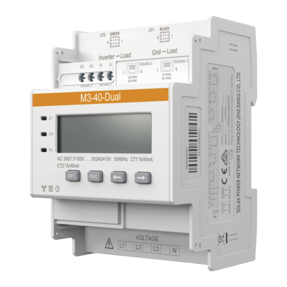
- Page 11 Product Overview M3-40-Dual Figure 2-3 Appearance of M3-40-Dual Table 2-3 Appearance description of M3-40-Dual No . Type Marking Definition L1, L2 and L3 UL terminal, connected to the L wires of the grid UN terminal, connected to the N wire of the grid CT1 BLACK Current input terminal, connected to the batch of CTs CT2 GREEN...
-
Page 12: Typical Networking Diagrams
Typical Networking Diagrams SolaX meters can be connected to inverters and other devices to form multiple types of power systems, and monitor and control the power consumption and storage of these systems. These meters can communicate with inverters through RS485 cables, and also be connected to Wi-BR for wireless data transmission. - Page 13 Typical Networking Diagrams M1-40 M1-40 can only be connected to single-phase inverters for power monitoring. NOTICE! Make sure the arrow on the CT is pointing at the inverter/load side from the gird side. wire L wire I* wire RS485A wire...
- Page 14 Typical Networking Diagrams Inverter Meter/COM 485A 485B Power Power distribution distribution Wi-BR Wi-BR STAXXXXXXXXXXXX APXXXXXXXXXXXX 485B 485A 485A 485B Grid INV/Load Grid Main breaker Load Figure 3-2 Wireless data transmission through Wi-BR...
- Page 15 Typical Networking Diagrams M3-40 M3-40 can be connected to both single-phase and three-phase inverters. When connected to single-phase inverter, make sure to connect the voltage output terminals of the inverter to terminal L1 and N of the meter. NOTICE! Make sure the arrow on the CT is pointing at the inverter/load side from the gird side. L1 wire IA1* wire IC1* wire...
- Page 16 Typical Networking Diagrams Inverter Meter/COM 485A 485B M3-40 Power Power Wi-BR Wi-BR distribution box distribution box APXXXXXXXXXXXX STAXXXXXXXXXXXX 485A 485B 485A 485B INV/Load Grid Grid Main breaker Load Figure 3-4 Wireless data transmission through Wi-BR...
- Page 17 Typical Networking Diagrams M3-40-Dual M3-40-Dual offers two channels that can be used to monitor two power circuits at the same time. This is helpful when you have two power generation equipement at home and want to monitor them both without need for installing another metering device. NOTICE! CTs clipped onto the bus voltage cables must be pointing at the inverter/load side from the grid side, and CTs clipped onto the branch voltage cableds must be pointing at the...
- Page 18 Typical Networking Diagrams Inverter power power Wi-BR Wi-BR distribution COM/Meter distribution APXXXXXXXXXXXX APXXXXXXXXXXXX 485A 485B 485A 485B 485A 485B INV/Load Grid Main breaker Grid Load Figure 3-6 Wireless data transmission through Wi-BR...
-
Page 19: Unpacking And Inspection
Accessories of each meter model are specified below. After unpacking, check the items against the packing list. If there is any part damaged or missing, contact your supplier. M1-40 5m COM cable M1-40 2m CT Document Figure 4-1 Packing list of M1-40... - Page 20 Unpacking and Inspection Table 4-1 Packing list of M1-40 Item Quantity Remarks M1-40 CT with 2m cable 5m communication cable For connecting inverters and Wi-BR with an RJ45 connector Document M3-40 M3-40 4-pin terminal block CT batch M3-40 5m COM cable...
- Page 21 Unpacking and Inspection Item Quantity Remarks 5m communication cable For connecting inverters and Wi- with an RJ45 connector Document M3-40-Dual 7-pin terminal block CT batch M3-40-Dual 5m COM cable Document Figure 4-3 Packing list of M3-40-Dual Table 4-3 Packing list of M3-40-Dual Item Quantity Remarks...
- Page 22 Unpacking and Inspection Item Quantity Remarks 5m communication cable For connecting inverters and Wi- with an RJ45 connector Document...
-
Page 23: Cable Connection
Cable Connection Cable Requirements For each meter model, we offer CT or CT batches with 2-meter cable, and a 5-meter communication cable with an RJ45 connector. In addition, you will need to prepare extra cables based on the table below. Table 5-1 Cable requirements Sectional Outer... -
Page 24: Connection Procedure
Step 2: Insert the conductors into the L and N terminals according to the meter markings, and then use a torch screwdriver to secure the connection. L wire N wire 7 mm 0.45 N·m Figure 5-1 Connecting power cables for M1-40... - Page 25 Cable Connection M3-40 & M3-40-Dual NOTICE! • M3-40 and M3-40-Dual meter models share the power cable connection procedure, but make sure the cables are connected conforming to the cable sequence markings. • When M3-40 and M3-40-Dual is connected to single-phase inverters, ensure that the voltage output cables are connected to L1 and N terminals.
-
Page 26: Ct Cable Connection
Grid INV/Load 0.45 N·m Figure 5-4 Connecting CT cables for M1-40 M3-40 & M3-40-Dual We offer plug-and-play CT batch for three-phase meters. You can directly plug the CT terminal into the CT port, and then clip the CTs respectively onto the L wires. -
Page 27: Communication Cable Connection
RS485A wire RS485B wire 0.45 N·m Figure 5-6 Connecting communication cable for M1-40 M3-40 & M3-40-Dual The three-phase meter models offer two types of communication terminals. You can connect the communication cable for these meters either through the RS485 terminal or... - Page 28 Cable Connection the RJ45 terminal based on on-site conditions. NOTICE! The communication cable connection procedure of all three-phase meter models are the same. The following diagram uses M3-40 for example. • Connection through RJ45 terminal The communication cable delivered with the meter already has PIN4 and PIN5 connected. Therefore, you can directly insert the RJ45 connector into the RJ45 terminal of the meter.
-
Page 29: Mechnical Installation
Mechnical Installation All these meters are designed to be installed onto the 35 mm DIN rail inside the power distribution box. WARNING! • Only the qualified personnel can perform the mechanical installation following local standards and requirements. • Before mounting the meter, make sure that the meter is in good condition and that the power has been cut off. -
Page 30: Lcd Display
Go to the previous item Go to the next item → M1-40 Figure 7-1 M1-40 display NOTICE! The minus sign (-) on the display means reverse active energy. Table 7-2 Parameters displayed on M1-40 Item Description Item Description Positive active Reverse active energy=2.200... - Page 31 LCD Display Item Description Item Description Active Power factor power=1.100 kW PFt=1.000 Communication Frequency= protocol: Modbus; 50.000 Hz Communication address: 1 Communication baud rate: 9600 M3-40 Figure 7-2 M3-40 display Table 7-3 Parameters displayed on M3-40 Item Description Item Description Positive active Reverse active energy=...
- Page 32 LCD Display Item Description Item Description Phase A Phase B current= current=5.000 A 5.001 A Combined phase Phase C active power= current=5.002 A 3.291 kW Phase A active Phase B active power=1.100 kW power=1.100 kW Combined phase Phase C active power factor power=1.100 kW PFt=1.000...
- Page 33 LCD Display M3-40-Dual Figure 7-3 M3-40-Dual display Table 7-5 Parameters displayed on M3-40-Dual Item Description Item Description Total energy of the Positive active circuits energy of Circuit =10000.00 kWh 1=10000.00 kWh Positive active Reverse active energy of Circuit energy of Circuit 2=10000.00 kWh 1=2345.67 kWh Reverse active...
- Page 34 LCD Display Item Description Item Description Phase A current of Phase B current of Circuit 2=5.000 A Circuit 2=5.001 A Combined phase Phase C current of active power of Circuit 2=5.002 A Circuit 1=3.291 kW Phase A active Phase B active power of Circuit power of Circuit 1=1.100 kW...
- Page 35 LCD Display Item Description Item Description Phase C power Frequency of factor of Circuit Circuit 1= 2=1.000 50.001 Hz Frequency of Current wiring Circuit 2= mode: 3P4W 50.001 Hz Circuit 1: Circuit 2: Communication Communication protocol: Modbus; protocol: Modbus; Communication Communication address: 1 address: 2...
-
Page 36: Parameter Setting
Set prameters for the meter to suit the operations of other devices through the buttons on the front panel. NOTICE! • Currently, M1-40 does not support setting parameters. Therefore, this chapter only applies to M3-40 and M3-40-Dual. • The following images of the displayed items are for reference only, and might differ from the display of the actual product. -
Page 37: Setting Procedure
Parameter Setting Parameter Value range Description Restore the meter to factory settings 0: No; • 0: Do not clear the meter settings 1: E; • 1: Restore the meter to factory settings Setting Procedure For ease of use, most parameters are preset in accordance with the requirements for operation with SolaX inverters upon delivery. - Page 38 Parameter Setting NOTICE! Password verification is required for parameter setting. The default password is 717. Setting the transformer current and voltage ratio The current ratio of the included CT model is 40, and it is preconfigured upon delivery. If there is any inconsistency, or if you have changed the CT model, follow the steps to set the current and voltage ratio.
- Page 39 Parameter Setting Setting the power grid type Set the power grid type to 3-phase 4-wire (3P4W) or 3-phase 3-wire (3P3W). Clearing historical data Restoring to factory settings...
-
Page 40: Troubleshooting
Troubleshooting Followings are common problems with the meter when used with inverters. When a problem occurs, check the questions below for possible reasons and solutions. For further assistance, contact SolaX after-sales service. 01 What if the inverter LCD or SolaXCloud reports a MeterFault alarm when the meter is connected to and enabled on the inverter? The inverter reports a MeterFault alarm when it fails to communicate with the meter. -
Page 41: 10 Technical Data
10 Technical Data Model M1-40 M3-40 M3-40-Dual Power grid type 1P2W 3P3W/3P4W 3P3W/3P4W Rated voltage 220V…240V 3*220/380V…3*240/415V 3*57.7/100V…3*240/415V Operating voltage 100 V~288 V 100 V~280 V 50 V~480 V Current *A/40 mA Recommended 100 A/40 mA; 100 A/40 mA; 200 A/40 mA; 400 A/40 mA; 600 A/40... -
Page 42: 11 Appendix
11 Appendix M1-40 can only be connected to single-phase inverters. It is compatible with the following single- phase inverters. While connecting the cables, pay special attention to the connector type and the pin number of the inverter. Connector Inverter series Terminal type Pin No. - Page 43 Appendix M3-40&M3-40-Dual M3-40 and M3-40-Dual can be connected to both single-phase and three-phase inverters. Therefore, besides the above the single-phase inverters, it is also compatible with the following three-phase inverters. Inverter series Terminal Type Connector type Pin No. Pin definition 485A •...
- Page 44 Appendix Inverter series Terminal Type Connector type Pin No. Pin definition 485A • X3-MEGA G2 Quick-connect • X3-FORTH terminal 485B 485A X3-AELIO RJ45 485B 485A X3-HYB G4 PRO RJ45 485B...
- Page 45 Contact Information AUSTRALIA UNITED KINGDOM Unit C-D Riversdale House, Riversdale 21 Nicholas Dr, Dandenong South VIC 3175 Road, Atherstone, CV9 1FA +61 1300 476 529 +44 (0) 2476 586 998 service@solaxpower.com service.uk@solaxpower.com TURKEY GERMANY Fevzi Çakmak mah. aslım cd. no 88 A Am Tullnaupark 8, 90402 Nürnberg, Karatay / Konya / Türkiye Germany...
- Page 47 SolaX Power Network Technology (Zhejiang) Co., Ltd. ADD.: No.278, Shizhu Road, Chengnan Subdistrict, Tonglu County, Hangzhou, Zhejiang, China E-mail: info@solaxpower.com www.solaxpower.com Copyright © SolaX Power Network Technology (Zhejiang) Co., Ltd. All rights reserved. 320101117101...
Need help?
Do you have a question about the M1-40 and is the answer not in the manual?
Questions and answers