
Related Manuals for Comelit Quadra 4893M


Summary of Contents for Comelit Quadra 4893M
- Page 1 Quadra 4893M F U L L T E C H N I C A L M A N U A L Join us in taking care of our planet...
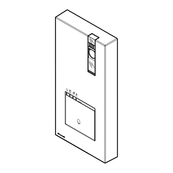
- Page 2 External entrance panel for Simplebus 2 system Surface-mounted door entry monitor entrance panel, Quadra series, for Simplebus 2 system. Die-cast aluminium front panel, wide-angle colour video camera and single LED for night-time lighting. Mechanical buttons with the option of setting 1 to 4 call buttons via DIP-switch.
- Page 3 Table of contents Notes for the installer Description Technical specifications Installation Changing nameplates Programming Operating distances Wiring diagrams Using the entrance panel relay on generic actuator control Variant with use of safety door lock Table of user codes...
-
Page 4: Notes For The Installer
| Table of contents | Notes for the installer 72° 72° 72° 72° 72° 72° 50 cm 50 cm 50 cm 50 cm 50 cm 50 cm 92 cm 92 cm 85° 85° The camera must not be installed in front of light sources, or in places where the filmed subject is against the light. - Page 5 | Table of contents | 8. DIP-SWITCH for function programming. 9. PR programming input/output switch. CNF programming confirmation switch. 10. Terminal block M1: LL bus line connection. RTE request to exit button input. COM common input for RTE and DO contacts. DO door open indication input.
-
Page 6: Technical Specifications
| Table of contents | Technical specifications GENERAL DATA Type Complete unit Height (mm) 195 Width (mm) 95 Depth (mm) 28 Product weight (g) 300 Product colour Grey RAL 9006, Black RAL9005 Surface mounting Yes COMPATIBLE SYSTEMS Simplebus 2 audio/video kit with power supply unit art. -
Page 7: Installation
| Table of contents | Installation OPEN You can download the free software (art. 1235A) to print the entrance panel name cards, using the adhesive pre-cut sheets available in our catalogue (art. 1217A). - Page 8 | Table of contents | Before securing the screw, make sure that you do not need to program the entrance panel and make sure that the metal front panel does not rub against other metal parts, with consequent risk of damage to its insulating coating. While the system is running, take care not to accidentally call users when replacing the nameplate labels.
-
Page 9: Changing Nameplates
| Table of contents | Changing nameplates... - Page 10 | Table of contents | Programming ENTRANCE PANEL SETTINGS f Permanently set the S1 DIP-switches corresponding to the function you want to program in accordance with the table below (you do not need to enter programming mode) FUNCTION The SE output and the C-NO relay are controlled by 2 separate buttons on the door entry monitor: the key button 1 2 3 4 (SE) and the generic actuator button (C-NO)
- Page 11 | Table of contents | PROGRAMMING CALL CODES FOR TWO-FAMILY AND FOUR-FAMILY VERSION f Make a note of the DIP-switch settings. f Set the code corresponding to the desired programming. 1 2 3 4 default 1 2 3 4 1 2 3 4...
- Page 12 | Table of contents | f Reset the DIP-switch settings.
- Page 13 | Table of contents | PROGRAMMING AN ADDITIONAL ENTRANCE PANEL With switching device art. 1405, only one additional entrance panel may be installed. Program the entrance panel as Main or Secondary • The Main entrance panel carries out lock-release (or actuator) commands only when it is in call or self-ignition mode.
- Page 14 | Table of contents | f Set the DIP switch according to your A-B-C system. Example= A 1404 1 2 3 4 1405 SYSTEM TYPE (A-B-C) DIP-SWITCH CODE 1404 cod. 32 1405 1 2 3 4 cod. 16 1405 1 2 3 4 cod.
- Page 15 | Table of contents | f Reset the DIP-switch settings.
- Page 16 | Table of contents | PROGRAMMING THE DESIRED CALL CODE f Make a note of the DIP-switch settings. f Set the call code of the apartment you wish to call (see Table of user codes) 1 2 3 4 Example: code 2 f Reset the DIP-switch settings.
-
Page 17: Disabling The Com-Rte Contact
| Table of contents | DISABLING THE COM-RTE CONTACT f Make a note of the DIP-switch settings. f Set the DIP-switches to position 206 (ON 2,3,4,7,8) in accordance with the addressing table 1 2 3 4 6 7 f Reset the DIP-switch settings. -
Page 18: Restore Factory Settings
| Table of contents | RESTORE FACTORY SETTINGS f Make a note of the DIP-switch settings. f Set the DIP-switches to position 254 (ON 2, 3, 4, 5, 6, 7, 8) 1 2 3 4... - Page 19 | Table of contents | f Reset the DIP-switch settings.
-
Page 20: Operating Distances
4893M 4893M A max. B max. E max. Art. 1216 Comelit Art. 4577/4579 1 mm² (Ø 1.2 mm AWG 17) 200 m 100 m (655 feet) (330 feet) UTP5 cat. 5 0.2 mm² (Ø 0.5 mm AWG 24) 100 m... -
Page 21: Wiring Diagrams
| Table of contents | Wiring diagrams CFP CFP 1209 110-240V 4893M 12 VAC/VDC 18 Ω MAX Max. 20 m. Local door-opener button. - Page 22 | Table of contents | 1216 CFP CFP 1214/2C CFP CFP 1214/2C CFP CFP 1214/2C CFP CFP 1214/2C 1209 110-240V 4893M 12 VAC/VDC 18 Ω MAX Max. 20 m. Local door-opener button.
- Page 23 | Table of contents | With switching device 1405 VIDEO ENTRY SYSTEM RISER 1405 1209 L1 L1 L2 L2 110-240V 4893M 4893M 12 VAC/VDC 12 VAC/VDC 18 Ω MAX 18 Ω MAX To program the entrance panel as Main or Secondary, refer to Programming an additional entrance panel on page 13.
- Page 24 | Table of contents | With switching VIDEO ENTRY SYSTEM RISER device 1404 1404 1 2 3 4 1 2 3 4 1 2 3 4 1209 1209 110-240V 110-240V 4893M 4893M Max. 20 m. Local door-opener button. The Door open indication function is not available. By using the switching device 1404, you can add one or more entrance panels to the kit.
- Page 25 | Table of contents | Max. 20 m. Local door-opener button. The Door open indication function is not available. The Self-ignition function is available, with toggle function between 2 external entrance panels.
- Page 26 | Table of contents | Using the entrance panel relay on generic actuator control Relay activation time C.NC.NO: 2 sec. (default) 12 VAC/VDC Default 18 Ω MAX 1209 1 2 3 4 The SE output and the C-NO relay are 4893M controlled by 1 single button on the door entry monitor: the key button...
- Page 27 | Table of contents | Table of user codes code DIP ON 1,2,3,4,5 1,3,4,5,6 1,2,4,5,7 1,4,5,6,7 1,2,3,5,8 1,3,5,6,8 1,2,5,7,8 2,3,4,5,6 3,4,5,7 2,4,5,6,7 4,5,8 2,3,5,6,8 3,5,7,8 1,2,3,4,5,6 1,3,4,5,7 123 1,2,4,5,6,7 153 1,4,5,8 183 1,2,3,5,6,8 213 1,3,5,7,8 2,3,4,5,7 3,4,5,6,7 2,4,5,8 4,5,6,8 2,3,5,7,8 1,2,6 95 1,2,3,4,5,7 125 1,3,4,5,6,7 155 1,2,4,5,8...
- Page 28 C E R T I F I E D M A N A G E M E N T S Y S T E M S w w w . c o m e l i t g r o u p . c o m 2nd edition 07/2024 Via Don Arrigoni, 5 - 24020 Rovetta (BG) - Italy code 2G40003206...
Need help?
Do you have a question about the Quadra 4893M and is the answer not in the manual?
Questions and answers