Table of Contents
Advertisement
Quick Links
Advertisement
Table of Contents

Subscribe to Our Youtube Channel
Related Manuals for ACOPOWER SGR-MP30011-2


Summary of Contents for ACOPOWER SGR-MP30011-2
- Page 1 Photovoltaic Inverter User Manual Model: SGR-MP30011-2...
-
Page 2: Table Of Contents
Contents INTRODUCTION Purpose Scope SAFETY INSTRUCTION OPERATION SECTION Features Basic System Architecture Product Overview INSTALLATION 04-10 Unpacking and Inspection Preparation Mounting the Unit 04-05 Battery Connection 05-06 AC Input/Output Connection 07-08 PV Connection 08-09 Final Assembly OPERATION 10-25 Power ON/OFF Operation and Display Panel LCD Display Icon 12-13... -
Page 3: Introduction
INTRODUCTION Purpose This manual introduces the assembly, installation, operation, and trouble shooting of the unit. Please read this manual carefully before installation and operation. Please keep this manual for future reference. Scope This manual provides safety and installation guidelines, as well as information on tools and wiring. -
Page 4: Operation Section
OPERATION SECTION Preface This is a multi-function inverter that combining functions of inverter, MPPT solar charger, and battery charger, providing portable uninterruptible power supply support. Its comprehensive large LCD display offers user-configurable and easy-accessible touch button operations, such as battery charging current, AC/solar charging priority, and acceptable input voltage based on different applications. -
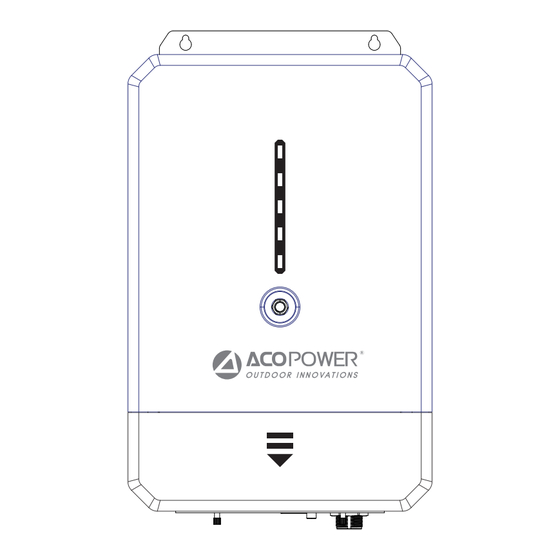
Page 5: Product Overview
Product Overview ON/OFF PV Input AC Input AC Output DC Output Circuit Breaker Charging Port RS485 Communication Port Output Socket Battery Input 120V AC/25A MAX PV INPUT AC INPUT AC OUTPUT DC OUTPUT 120V/25A MAX 120V/2000W MAX BATTERY CAMM — 03 —... -
Page 6: Installation
INSTALLATION Unpacking and Inspection Before installation, please check the unit to ensure that there is no damage inside the packaging. You should receive the following items within the package: The unit x1 User manual x1 Preparation Before connecting all wiring, please remove the two self-twisting screws on the front cover, as shown in the following figure. -
Page 7: Battery Connection
Ring Terminal shown below. Recommended battery cables and terminal sizes Ring Terminal Typical Battery Wire Torque Model Dimensions Cable Amperage Capacity Size Value mm² D(mm) L(mm) M(mm) 12V/300AH 1*2/0 SGR-MP30011-2 300A 18.2 2~3Nm Or more(Inclusive) — 05 —... - Page 8 Please follow the steps below to connect the battery: 1. Assemble the battery ring terminals according to the recommended battery cables and terminal sizes. 2. Connect all battery packs based on the requirements of the unit. Caution: Please use sealed lead-acid batteries (AGM, GEL, Flooded) or lithium batteries only.
-
Page 9: Ac Input/Output Connection
4.To reduce the risk of injury, please use proper cables with the following recommended sizes. Recommended AC cable requirements Model Gauge Torque Value SGR-MP30011-2 8 AWG 1.2~1.6Nm Please follow the steps below to achieve AC input/output connection: 1. Before making AC input/output connections, be sure to disconnect the DC protector or switch. -
Page 10: Pv Connection
For the safe system and efficient operation, it is very important to using suitable cables to connect the battery. To reduce the risk of injury, please use the proper cables with the following recommended sizes. Model Wire Size Calbe(mm²) Torque Value(Max) SGR-MP30011-2 10AWG 1.2Nm — 08 —... - Page 11 PV Module Selection: When selecting proper PV modules, please be sure to consider below parameters: 1.The open circuit voltage (Voc) of the PV module does not exceed 300V. 2. The operating voltage (Voc) of the PV module should be higher than 30V. Inverter Model 3.0KW Max.
-
Page 12: Final Assembly
Final Assembly After connecting all wires, please put bottom cover back and tighten two screws, as shown below: OPERATION Power ON/OFF Once the unit has been properly installed and the batteries are connected well, simply press ON/OFF switch(located on the button of the case) to turn on the unit. —... -
Page 13: Operation And Display Panel
Operation and Display Panel The operation and display panel, shown in below chart, is on the front panel of the inverter. It includes three indicators, four function keys and a LCD, indicating the operating status and input/output power information. LCD Screen LED Indicators Function Keys LED Indicator... -
Page 14: Lcd Display Icon
LCD Display Icon Icon Function Description Input Source Information Indicates the AC input. Indicates the PV input. Indicates input voltage, input frequency, PV voltage, battery voltage and charger current. Configuration Program and Fault Information Indicates the program setting. Indicates the warning and fault codes. Warning: Flashing with warning code. - Page 15 It will present battery capacity while in Battery Mode Load Percentage Battery Voltage LCD Screen Display <1.717V/cell 1.717V/cell~1.8V/cell Load > 50% 1.8~1.883V/cell >1.883 V/cell <1.817V/cell 1.817V/cell ~ 1.9V/cell 50% > Load > 20% 1.9~1.983V/cell >1.983 <1.867V/cell 1.867V/cell ~ 1.95V/cell Load < 20% 1.95~2.033V/cell >2.033 Load Information...
-
Page 16: Lcd Setting
LCD Setting After holding the ENTER button for 3 seconds, the unit will enter the setup mode. Press the 'UP' or 'DOWN' buttons to select the configuration program. Then press the 'ENTER' button to confirm your selection or ESC button to exit. Setting Programs Program Description... - Page 17 AGM (default) Flooded lithium battery Battery type User-Defined If "User-Defined”is selected, battery charge voltage and low DC cut-off voltage can be set up in program 26,27 and 29. Restart disable Restart enable Auto restart when (default) overload occurs Restart disable Restart enable (default) Auto restart when over temperature occurs...
- Page 18 If this inverter/charger is working online, Standby or Fault mode, charger source can be programmed as below: Solar energy will charge battery as first priority.Utility Solar first will charge battery only when solar energy is not available. Solar and Utility Charger source priority: Solar energy and utility will charge battery at To configure charger...
- Page 19 12V model default setting: 10.5V BATT Low DC cut-off voltage If self-defined is selected in program 5, this program can be set up. Setting range is from 10.0V to 12.0V (12V model). Increment of each click is 0.1V. Low DC cut-off voltage will be fixed to setting value no matter what percentage of load is connected.
-
Page 20: Display Setting
Display Setting The LCD display information will be switched in turns by pressing "UP" or "DOWN" button. The selectable information is switched as below order: input voltage, input frequency, PV voltage, MPPT charging current, MPPT charging power, battery voltage, output voltage, output frequency, load percentage, load in VA,load in Watt, DC discharging current, main CPU Version. - Page 21 Battery voltage/ Battery voltage=13.5V, DC discharging current discharging current=5A Output frequency Output frequency=60Hz Load percentage Load percentage=70% When connected load is lower than 1kVA ,load in VA will present xxxVA like below chart. Load in VA When load is larger than 1kVA, load in VA will present x.xkVA like below chart.
-
Page 22: Operating Mode Description
Operating Mode Description Operating Mode Description LCD display Description Charging by utility and PV energy. Standby mode / Power saving mode Charging by utility. Note: *Standby mode: The No output is inverter is not turned on yet but at this time, the supplied by the inverter can charge unit but it still can... - Page 23 No Charging Charging by utility and PV energy. The unit will provide output power from the mains. It will also charge the battery in by pass mode. Charging by utility. If " SUB " is selected as output source priority and solar energy is not sufficient to provide the load, solar energy and the utility will provide the loads and charge the battery at the same time.
-
Page 24: Battery Equalization Instruction
Power from battery and PV energy. PV energy will supply power to the loads and charge battery at the same time. The unit will provide Battery Mode output power from Power from battery only. battery and PV power. Power from PV energy only. Battery Equalization Description Equalization function is added into charge controller, it reverses the buildup of negative chemical effects like stratification, a condition where acid concentration is greater at... - Page 25 Equalize Voltage Float Voltage BULK ABSORPTION FLOAT EQUALIZE FLOAT Equalize charging time and time out In Equalize stage, the controller will supply power to charge battery as much as possible until battery voltage raises to battery equalization voltage. Then, constant-voltage regulation is applied to maintain battery voltage at the battery equalization voltage, The battery will remain in the Equalize stage until setting battery equalized time is arrived.
-
Page 26: Fault Reference Code
Fault Reference Code Fault Code Fault Event Icon On Fan locking protectiona Over temperature Battery voltage is too high Battery voltage is too low Output short circuited or over temperature is detected by internal converter components. Output voltage is too high. Overload time out Bus voltage is too high Bus soft start failed... -
Page 27: Warning Indicator
Warning Indicator Warning Indicator Warning Event Audible Alarm Icon flashing Fan is locked when Beep twice every second inverter is on. Battery is over-charged Beep twice every second Low battery Beep twice every second Overload Beep twice every second Output power derating Beep twice every second Solar charger stops due to low battery. -
Page 28: Specifications
SPECIFICATIONS 1. SPECIFICATION Rated Output Power 3000VA/W Solar Panel Input PV 30~300V/20A 3000VA/W Max AC 90~145V 55~65HZ charging power 3000VA/W MAX AC/Generator Input AC 90~145V Frequency55~65HZ Charging Power 3000VA/W MAX AC Input Bypass Function Have Pure Sine Wave Output; AC Continuous Output: 3000VA/W Max AC Output AC Max Output: 3600W@5 seconds AC Voltage: 120VAC±10%... - Page 29 2. Charger Output PARAMETERS Note: Test ambient temperature 25℃±3℃ Outputs Parameters Item Input source for charging state PV input and AC mains or generator input/(default PV priority) Charging current 150A(Max) PV input current 20A(Max) AC Input Current 30A(Max) Charge efficiency ≥90% PF Value ≥0.997...
- Page 30 3. INVERTER PARAMETERS Note: Test ambient temperature 25℃±3℃ Range Typical Unit Remark Item In Bypass Mode, the Output Voltage output voltage follows the Range(V) mains voltage. In Bypass Mode, the Output Frequency output frequency follows 60±5Hz the mains frequency. Output Waveform Pure Sine wave Resistive load 3000W MAX...
- Page 31 Collecting temperature PV input current Inverter Output Power PV input Output Temperatures Fan Speed Fan Speed Fan Speed current Power ≥55℃ ≥5A ≥300W Starting cooling ≥65℃ ≥10A ≥600W fan conditions ≥75℃ 100% ≥15A 100% ≥1200W ≥1800W ≥75℃ 100% ≥15A 100% ≥2400W 100% Table 4 General...
-
Page 32: Trouble Shooting
TROUBLE SHOOTING Explanation/ Problem LCD/LED/Buzzer What to do Possible cause LCD/LED and buzzer Unit shuts down will be active for 3 The battery voltage is 1. Re-charge battery. automatically seconds and then too low(<1.91V/Cell) 2. Replace battery. during start up. complete off. -
Page 33: Attachment: Approximate Backup Timetable
Output abnormal 1. Reduce the connected load. (Inverter voltage below Fault code 06/58 2. Return to repair center than 190Vac or is higher than 260Vac) Internal components Return to repair center. Fault code 08/09/53/57 failed. Fault code 51 Over current or surge. Restart the unit, if the error Fault code 52 Bus voltage is too low.
Need help?
Do you have a question about the SGR-MP30011-2 and is the answer not in the manual?
Questions and answers