
Summary of Contents for RAA ROBUSTMOTION RM-RPLA-11-50-2-R-V
- Page 1 PRODUCT USER MANUAL ® ROBUSTMOTION ELECTRIC LINEAR ACTUATOR SERIES Please read this MANUAL carefully before using the product. DOCCODE: ELAPUM2409...
-
Page 2: Preface
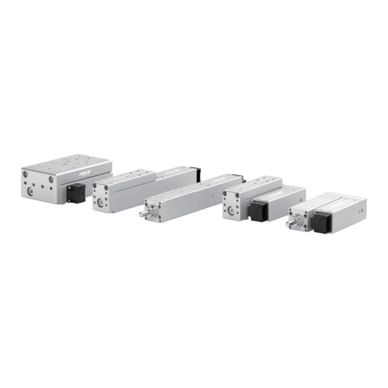
PREFACE PREFACE OVERVIEW The Robustmotion® Electric Linear Actuator Series, with its diverse forms and a wide range of sizes and models, comprehensively covers the diverse needs of industrial automation. The product line includes Straight Linear Actuators (RM-SLA), Folding Linear Actuators (RM-RLA), Straight Platform-Type Linear Actuators (RM-PLA), Folding Platform-Type Linear Actuators (RM-RPLA), and Wide Platform-Type Linear Actuators (RM-WRPLA), among others. -
Page 3: Table Of Contents
CONTENTS Contents PREFACE ..........................1 Product Introduction ....................4 Debugging Preparations ....................5 Product Catalogue ............................5 Matching of Controller and Actuator ......................5 Extra Items Prepared by User ........................6 RMS Software ..............................6 Wiring Of the Actuator....................7 Wiring Instructions ............................7 Wiring Position and Wiring Method of the Actuator ...................7 Wiring Instructions for the Actuator ......................8 Integrated Connection Panel Wiring Instructions (ITG Series) ..............9 3.4.1... - Page 4 CONTENTS 4.7.1 Left Side Status Bar ............................34 4.7.2 Right Side Status Bar ............................34 Parameter Editor Interface .........................35 4.8.1 Change Station Number & Baudrate ........................35 4.8.2 Change IP Address ..............................36 4.8.3 Change MAC Address ............................36 4.8.4 External I/O Input and Output Configuration ....................37 4.8.5 Pulse Parameter Adjustment ..........................37 4.8.6...
-
Page 5: Product Introduction
PRODUCT INTRODUCTION Product Introduction Robustmotion® Electric Linear Actuator Series The Robustmotion® Electric Linear Actuator Series offers a variety of models, including Straight Linear Actuators (RM-SLA), Folding Linear Actuators (RM-RLA), Straight Platform-Type Linear Actuators (RM-PLA), Folding Platform- Type Linear Actuators (RM-RPLA), and Wide Platform-Type Linear Actuators (RM-WRPLA), among other forms. Each product is available in different strokes, accuracies, and size specifications. -
Page 6: Debugging Preparations
DEBUGGING PREPARATIONS Debugging Preparations Product Catalogue Please check the "Sales Dispatch Note" in the packaging box (using the product model RM-RPLA-11-50 as an example) to confirm whether it corresponds with the product model and quantity received. SAMPLE Sales Dispatch Note Customer Name: xxx Co., Ltd. -
Page 7: Extra Items Prepared By User
DEBUGGING PREPARATIONS Please check whether the serial numbers on the labels of the controller and the electric actuator match each other, and the controller model must be completely consistent with the actuator model. Misuse is not allowed, as it may cause abnormal actuator movements. -
Page 8: Wiring Of The Actuator
WIRING OF THE ACTUATOR Wiring Of the Actuator • Please perform wiring on the actuator while it is powered off. Do not turn on the power before the wiring is complete, as plugging in with power can damage the actuator or the controller. •... -
Page 9: Wiring Instructions For The Actuator
WIRING OF THE ACTUATOR 2. Motor Direction - Optional L / R L - Left R - Right The motor direction is on The motor direction is on left side, facing the right side, facing the front end of the actuator. front end of the actuator. Wiring Instructions for the Actuator To ensure the stability of cable connections during the use of the product, it is recommended to use flexible fixing devices to secure the cables. -
Page 10: Integrated Connection Panel Wiring Instructions (Itg Series)
WIRING OF THE ACTUATOR Integrated Connection Panel Wiring Instructions (ITG Series) The "integrated connection panel" is intended for quick debugging by first-time users and is generally not required for regular use. 3.4.1 Upper Computer Software Debugging Wiring Method Power Supply Use the matching cable for connection Actuator Power Supply RM-RPLA-ITG... -
Page 11: Bus Control Wiring Method
WIRING OF THE ACTUATOR 3.4.3 Bus Control Wiring Method IO Presence Signal IO Control Signal Power Supply I/O Power Supply Use the matching cable for connection Actuator Power Supply Power Supply RM-RPLA-ITG 3.4.4 Wire Sequence Description for the Actuator Group Color Definition Description... -
Page 12: Circuit Diagram Wiring Illustration
WIRING OF THE ACTUATOR 3.4.6 Circuit Diagram Wiring Illustration 1. The ITG (Integrated) series products natively supports NPN. When the PLC I/O type is NPN, the wiring method is as follows: ITG Series Products I/O INPUT NPN OUTPUT COM I/O OUTPUT NPN INPUT 2. -
Page 13: Wiring Instructions For The Actuator And Rm-Cep Controller
WIRING OF THE ACTUATOR Wiring Instructions for the Actuator and RM-CEP Controller 1. ROBUSTION® Intelligent Electric Linear Actuators are typically paired with the RM-CEP series controllers, the parameter description of which is shown in the table below. Model RM-CEP-A-TCP-S RM-CEP-A-CAN-S RM-CEP-A-PN-S RM-CEP-A-EIP-S RM-CEP-A-ECAT-S Drive Current (A) Rated Voltage (V) DC24±10% DC24±10% DC24±10% DC24±10% DC24±10% I/O Control Support Support Support Support Support Pulse Control Support Support Support... -
Page 14: Bus Control Wiring Instructions
WIRING OF THE ACTUATOR Bus Control Wiring Instructions 3.6.1 Wiring Instructions for RM-CEP-X-ECAT Controller Model When using the RM-CEP-X-ECAT model controller, the port definitions are as follows: EtherCAT IN • CN8 and CN9 do not support for blind plugging. EtherCAT OUT •... -
Page 15: Wiring Instructions For Rm-Cep-X-Tcp / Rm-Cep-X-Pn / Rm-Cep-X-Eip Controller Models
WIRING OF THE ACTUATOR 3.6.2 Wiring Instructions for RM-CEP-X-TCP / RM-CEP-X-PN / RM-CEP-X-EIP Controller Models When using the RM-CEP-X-TCP , RM-CEP-X-PN , and RM-CEP-X-EIP controllers, the port definitions are as follows: Modbus RTU *Factory-supplied USB to RS485 debugging adapter • CN8 and CN9 support for port blind plugging, allowing insertion into any port of your choice. •... -
Page 16: Wiring Instructions For Rm-Cep-X-Can Controller Model
WIRING OF THE ACTUATOR 3.6.3 Wiring Instructions for RM-CEP-X-CAN Controller Model When using the RM-CEP-X-CAN controller, the port definitions are as follows: Bus Port *Factory-supplied USB to RS485 debugging adapter • CN8 and CN9 support for port blind plugging, allowing insertion into any port of your choice. • When debugging with RMS Software, please connect to the computer or industrial control machine using the factory-supplied USB to RS485 debugging adapter. -
Page 17: I/O Control Wiring Instructions
WIRING OF THE ACTUATOR I/O Control Wiring Instructions The K1 red port is the switch for enabling I/O control and pulse control, and CN6 is a 26-pin port serving as the interface for I/O control and pulse control. The explanation of the K1 switch settings and the pinout of CN6 are shown as follows: Dip Switch Description (K1 Red port) Sketch Map - (1) - Page 18 WIRING OF THE ACTUATOR 1. When using I/O control, firstly ensure that the 2nd dip switch on Port K1 is set to the ON position to enable the I/O control switch. 2. Then, determine whether the I/O signal of the upper computer is NPN or PNP. After confirmation, connect the pins of CN6 to the input and output I/O ports of the upper computer as shown in the figure below.
-
Page 19: Pulse Control Wiring Instructions
WIRING OF THE ACTUATOR Pulse Control Wiring Instructions 1. When using pulse control, first set the 2nd and 3rd dip switches on port K1 of the controller to the ON position to enable the I/O and pulse control switches. 2. Then determine whether to use a 24V pulse signal or a 5V pulse signal. After confirmation, connect the pins of CN6 to the upper computer's pulse control interface as shown in the diagram below. -
Page 20: Power Supply Module Wiring Instructions
WIRING OF THE ACTUATOR 4. Principle of Pulse Control 5V Pulse 24V Pulse Rated Load Voltage DC5V Rated Load Voltage DC24V Specifications Maximum Input Pulse Power 500KPPS Maximum Input Pulse Power 200KPPS Insulation Method Optocoupler Insulation Method Optocoupler Direction Signal Pulse Signal Power Supply Module Wiring Instructions 1. -
Page 21: Rms Software Debugging Platform Usage
RMS SOFTWARE DEBUGGING PLATFORM USAGE RMS Software Debugging Platform Usage (www.rmaxis.com/en) Please visit the official website of RobustMotion and download the software from the Download page, or contact our after-sales engineer to obtain the RMS debugging software package. Through the RMS software debugging platform, users can set motion commands, modify parameters, and monitor control according to actual process requirements. -
Page 22: Device Connection
RMS SOFTWARE DEBUGGING PLATFORM USAGE Device Connection For electric actuator debugging, the Modbus RTU communication protocol is typically selected due to its straightforward mechanism for monitoring actuator movement and facilitating initial diagnostics. Ensure that the USB-to-485 adapter for debugging is properly connected to both the controller and the PC. For integrated models, consult the [3.2.5 Integrated Connection Panel Wiring Instructions];... -
Page 23: Modbus Tcp Connection Type
RMS SOFTWARE DEBUGGING PLATFORM USAGE 4.3.2 Modbus TCP Connection Type 1. [Connection Type], Select "Modbus TCP". 2. [Connection Config], IP address: 192.168.0.233 (factory default); port: 502 (factory default); station ID: 1 (factory default). 3. Click [Next]. -
Page 24: Overview Of Main Interface Functions
RMS SOFTWARE DEBUGGING PLATFORM USAGE 4.3.3 Overview of Main Interface Functions The presence of the navigation bar on the left side of the interface, as depicted in the figure below, signifies that the software has established a successful connection with the actuator/controller. Upon each connection, the software automatically retrieves the current parameters from the controller. -
Page 25: Command Editor
RMS SOFTWARE DEBUGGING PLATFORM USAGE Command Editor Select 'Command Editor' from the navigation bar to access the interface below. This interface is the primary tool for actuator control, command configuration, and motion status display, and is one of the most frequently utilized features in the system. - Page 26 RMS SOFTWARE DEBUGGING PLATFORM USAGE Command Items Feature Introduction [Backward/ It is the JOG movement mode of the actuator, used when fine-tuning the position of the actuator is needed. [Backward] is for JOG-, [Forward] is for JOG+. Forward] [Stop] Used to stop the actuator's instructed movement. The Initialize action is a must-do operation after the actuator is powered on or restarted after power off.
-
Page 27: Detailed Explanation Of Command Types
RMS SOFTWARE DEBUGGING PLATFORM USAGE 4.4.2 Detailed Explanation of Command Types 1. [Absolute Move] Command The Absolute Move Command is a motion command for the actuator to move to a set position using the origin as a reference point. Command Parameters Parameter Description The target position for "Absolute Move", set the value to be less than the "Maximum Stroke Value"... - Page 28 RMS SOFTWARE DEBUGGING PLATFORM USAGE 3. [Pushing] Command The Pushing Command refers to starting from the current position, setting a movement at a rated output (current percentage) for a certain distance until the force reaches the set value and then maintaining it. •...
-
Page 29: Command Editing Examples
RMS SOFTWARE DEBUGGING PLATFORM USAGE Command Editing Examples 4.5.1 Rapid Positioning Commonly used for the linear actuator to quickly position to the push-pull location or the pre-push-pull location. 1. Example One: [Absolute Move] For example, adjustments are needed for the posture of the RM-RPLA-10-50 (with a stroke of 50mm) electric linear actuator. Currently, the electric linear actuator is at the 0mm position, as shown in Figure 1;... - Page 30 RMS SOFTWARE DEBUGGING PLATFORM USAGE 2. Example Two: [Relative Move] For example, adjustments are needed for the posture of the RM-RPLA-10-50 (with a stroke of 50mm) electric linear actuator. Currently, the electric linear actuator is at the 0mm position, as shown in Figure 5; to execute the "Relative Move" command to extend the electric linear actuator to the maximum allowed extension, i.e., the electric linear actuator needs to move to the upper limit position of 50mm, as shown in Figure 6.
-
Page 31: Rapid And Flexible Pressing
RMS SOFTWARE DEBUGGING PLATFORM USAGE 4.5.2 Rapid and Flexible Pressing Commonly utilized for the swift and compliant movement of workpieces with the linear actuator. Note:Electric linear actuators must not operate using solely the "Absolute Move" or "Relative Move" command to push or pull workpieces, as this will result in an alarm. 1. - Page 32 RMS SOFTWARE DEBUGGING PLATFORM USAGE 2. Example Two: [Absolute Move] +Reverse [Pushing] For example, we are currently using the RM-NPLA-10-50 (with a stroke of 50mm) electric linear actuator to press the bearing into the bearing seat with constant force and flexibility. The electric linear actuator is currently at position 50mm, and the distance between the electric linear actuator end press head and the bearing is 36mm, as shown in Figure 14.
-
Page 33: Offline Data Collection Interface
RMS SOFTWARE DEBUGGING PLATFORM USAGE Offline Data Collection Interface The offline data collection interface can collect real-time data such as current position, current output, homing position, and current force, and generate a line graph of data and time. It also allows for the export of data to Excel for analysis. 1. - Page 34 RMS SOFTWARE DEBUGGING PLATFORM USAGE 3. Curve Data Data collection commands allow for direct [Start current collect], [Start persistence collect], and also collection targeting a specific Command. By moving the mouse, you can view the Select the icon, and after clicking, you can choose a changes and values of the current position period on the curve for more specific data analysis.
-
Page 35: Status Monitor Interface
RMS SOFTWARE DEBUGGING PLATFORM USAGE Status Monitor Interface You can observe the current motor actuator's action execution status (Boolean quantity) and the input/output status of external I/O in the [Status Monitor] interface. 4.7.1 Left Side Status Bar The left side Status Bar shows the current action execution status of the motor, with ① as the status parameter name, and ②... -
Page 36: Parameter Editor Interface
RMS SOFTWARE DEBUGGING PLATFORM USAGE Parameter Editor Interface 4.8.1 Change Station Number & Baudrate Firstly establish a connection with the controller via the Modbus RTU. Upon successful connection, access the [Parameter Editor] interface. Within the Parameter Editor, navigate to the "modbus.slave" setting to modify the controller's station address, ensuring it falls within the permissible range of 1 to 255. -
Page 37: Change Ip Address
RMS SOFTWARE DEBUGGING PLATFORM USAGE 4.8.2 Change IP Address If using Modbus TCP communication, it is necessary to change the controller's IP address. First, connect to the controller using Modbus RTU. After the connection is complete, click on [Parameter Editor] and search for "IP" to change the controller's IP address. -
Page 38: External I/O Input And Output Configuration
RMS SOFTWARE DEBUGGING PLATFORM USAGE 4.8.4 External I/O Input and Output Configuration When using I/O control, if you need to configure external I/O mapping within the controller, first connect the software using Modbus RTU or other methods. In [Command Editor], search for "I/O" to find [physical_io.input_map_0] and [physical_io.output_map_0]. [physical_ io.input_map_0] corresponds to IN0 in the actual I/O wiring of the actuator, and [physical_io.output_map_0] corresponds to OUT0 in the actual I/O wiring of the actuator. -
Page 39: Power-Up Home Position Setting
RMS SOFTWARE DEBUGGING PLATFORM USAGE 4.8.6 Power-Up Home Position Setting After the actuator performs the "Pushing" (fingers open), do not use the "Initialize" command to open it. Instead, set an "Absolute Move" to "0mm" to achieve "returning to the origin" or move to the desired position. The actuator is set to automatically return to the home position by default before leaving the factory, and manual operation is generally not required. -
Page 40: I/O Mapping Interface
RMS SOFTWARE DEBUGGING PLATFORM USAGE I/O Mapping Interface [I/O Mapping] is another convenient method for configuring I/O input and output. Click on [I/O Mapping] in the left navigation bar, and by connecting the input and output parameters on the left and right with the I/O interface in the center, you can associate the I/O interface with the required functions to achieve I/O customization. -
Page 41: Modbus Rtu Communication Guide
MODBUS RTU COMMUNICATION GUIDE Modbus RTU Communication Guide When using Modbus RTU communication, the corresponding function codes and addresses are required to control the motion of the electric linear actuator and to modify the parameters of the electric linear actuator. Note: The Modbus addresses used in the examples are in decimal format. - Page 42 MODBUS RTU COMMUNICATION GUIDE 1. If you need to use the electric linear actuator to press the workpiece, you must turn on the torque mode switch; only after it is turned on can pressing be performed, otherwise the electric linear actuator will generate an error;...
- Page 43 MODBUS RTU COMMUNICATION GUIDE Command Type Sequence Number Explanation Command Type Number None Taking Command Sequence Number 0 as an example: the Modbus address Set Home for the Command type is 5000. Delay When 5000 equals 1, the Command Absolute Move type is for setting the home position.
-
Page 44: Function Code
MODBUS RTU COMMUNICATION GUIDE 5.1.3 04H Function Code The 04H function code is for reading input registers, used to read one or more 16-bit values from the input registers of the slave device. The 04H function code can be used to read the current position (address: 0), velocity (address: 2), and force sensor readings (address: 16), with each data point occupying two registers. -
Page 45: Modbus Communication Message Example
MODBUS RTU COMMUNICATION GUIDE Modbus Communication Message Example Modbus RTU (Remote Port Unit) communication message format adheres to a strict binary format, suitable for serial communication and particularly common in device communication within industrial automation environments. Below are the general components of a Modbus RTU message: Name Function A byte, ranging from 0x00 to 0x7F (0 to 247 in decimal), with the 0x00 address typically used for broadcasting, and... -
Page 46: Read Current Alarm Signal/Action Completion Signal
MODBUS RTU COMMUNICATION GUIDE 5.2.2 Read Current Alarm Signal/Action Completion Signal 01 02 00 00 00 01 B9 CA(Read Current Alarm Status) • 01 represents the slave device address, indicating that the message is sent to the device with station number 1. •... -
Page 47: Trigger Error Reset/Servo Toggle/Command Stop/Force Reset(Precision Torque Control)/Initialize/Execute
MODBUS RTU COMMUNICATION GUIDE If you need to write the floating-point number 20 into the controller, first convert 20 into a hexadecimal number. The hexadecimal equivalent of the floating-point number 20 is 41 A0 00 00, and after endian conversion, it becomes 00 00 41 A0. -
Page 48: Positioning Mode User Guide
MODBUS RTU COMMUNICATION GUIDE Positioning Mode User Guide 5.3.1 Introduction to Positioning Mode Positioning Mode, also known as Position Mode, requires the input of parameters such as distance, acceleration, and Velocity before the target position parameter is written. Once the target position parameter is written, the actuator will immediately execute the action without the need for a trigger signal;... -
Page 49: Modbus Rtu Example
MODBUS RTU COMMUNICATION GUIDE 5.3.2 Modbus RTU Example (Execute Positioning/Pushing-Pulling Actions Using Positioning Mode) 1. Modify Parameters and Perform "Absolute Move" (Suitable for Quick Positioning or Rapid Approach of the electric linear actuator): Example: Modify the target position, Velocity, acceleration, and torque to drive the electric actuator in "Absolute Move". - Page 50 MODBUS RTU COMMUNICATION GUIDE 2. Modify Parameters and Perform "Pushing" (Suitable for Pushing and Pulling Workpieces with the Electric Linear Actuator) Example: Modify the target position, Velocity, acceleration/deceleration, and torque to drive the electric actuator in "Pushing". Target Action Parameters Target Position(mm) Velocity(mm/s) Acceleration(mm/s²) Torque 0.5(50%) • Set the Velocity to 20mm/s Send:01 10 08 EE 00 02 04 00 00 41 A0 2B 83 Return:01 10 08 EE 00 02 23 9D •...
-
Page 51: Positioning Mode Precautions(Q&A
MODBUS RTU COMMUNICATION GUIDE 5.3.3 Positioning Mode Precautions(Q&A) Q1: What should be considered when reading and writing data? A1: When reading and writing data, it is essential to ensure the use of the correct data types. Incorrect data types may lead to improper data parsing or abnormal actuator responses. Q2: How can you determine if the electric actuator has reached the target position in positioning mode? A2: To determine if the positioning mode has reached the target condition, the host computer needs to read and compare the deviation between the current position and the target position (±0.1mm), and when the... -
Page 52: Maintenance
MAINTENANCE Maintenance Maintenance and Service General Principles 6.1.1 First Time Use Before the initial use, please confirm whether the interval from the date of receipt to the first use exceeds half a month (reduce appropriately in winter). If it does, it is recommended to apply a small amount of WD-40 rust- preventing lubricant to the actuator's screw rod, guide rail, and other transmission components before use, and move back and forth 3-5 times to allow the lubricant to fully contact the transmission components, ensuring the actuator is in optimal condition. -
Page 53: Regular External Cleaning And Lubrication
MAINTENANCE Regular External Cleaning and Lubrication Guide components of push rods and similar products are exposed to the air and typically accumulate dust or other dark contaminants during the general maintenance cycle. It is recommended to regularly clean the product itself and the surrounding environment, as well as to lubricate as needed. -
Page 54: Regular Self-Inspection
MAINTENANCE Next, move the push rod to approximately 15mm of travel, use a wrench (13mm) to grip the flat slot of the telescopic rod, then use a hexagonal wrench (matching the size of the front end screw hole) to loosen and remove the screw at the front end of the push rod, as shown in Figure 5. -
Page 55: Product Disclaimer Statement
PRODUCT DISCLAIMER STATEMENT Product Disclaimer Statement Dear Customer, First and foremost, we extend our heartfelt gratitude for choosing products from Foshan Augmented Intelligence Technology Co., Ltd. (hereinafter referred to as "we" or "our company"). This disclaimer aims to clarify the potential risks and responsibilities associated with the use of our products, ensuring that the rights and interests of both parties are effectively protected. - Page 56 Feel Free to Contact: + 86 13316309592 E-mail:Overseas@rmaxis.com ADD: 1st Floor, No. 20, Shunxiang Road, XinjiaoCommunity, Daliang Street, District, Foshan City, Guangdong Province, China Declaration: Users should thoroughly assess whether the product meets their specific requirements before use, and strictly follow operating procedures and safety manuallines during use; any indirect damages, special damages, incidental damages, or consequential damages caused by improper operation, misuse, unauthorized Find more at www.rmaxis.com/en modification, or use beyond the scope of the product shall be borne by the users themselves.
Need help?
Do you have a question about the ROBUSTMOTION RM-RPLA-11-50-2-R-V and is the answer not in the manual?
Questions and answers