Table of Contents
Advertisement
Quick Links
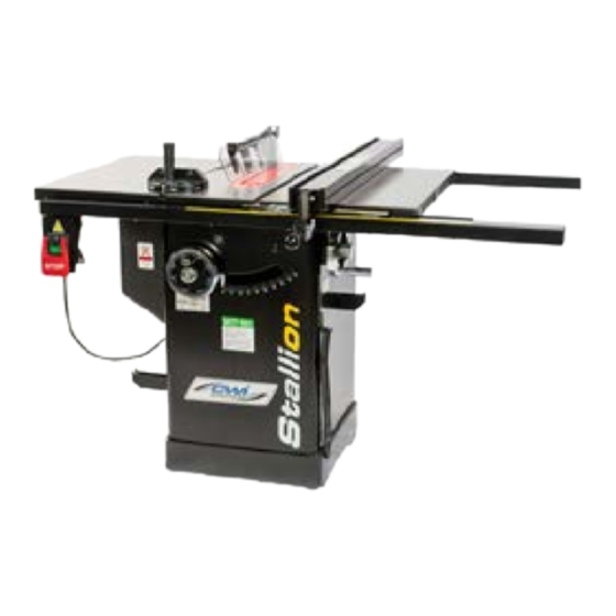
Stallion CWI-T1002(L)
Setup and Operation Manual
Specifications
• Saw Blade: 10" diameter w/ 5/8" bore (not included)
• Arbor tilt range: 0° to 45° (left tilt)
• Maximum depth of cut at 90°: 3-1/8"
• Maximum depth of cut at 45°: 2 1/4"
• Max. rip to right of blade: 30" (T1102L: 50")
• Max. rip to left of blade: 13"
• Dado capacity: 13/16"
• Fence: Steel w/ anodized aluminum sides, T-style, 41-3/8" x
3-7/8"
• Dust port diameter: 4"
• Arbor speed: 4200 RPM
• Table height: 36" (914 mm)
• Table size (w/ extension wings): 44" x 27"
• Floor Space: 44" x 61" x 40" (T1002L: 44" x 81" x 40")
• Motor (pre-wired 120V): 1.5 HP, 120/240V 15/7.5 A
• Shipping weight: 377 lbs (T1002L: 384 lbs)
T1002 w/ 30" fence
Features
• Combination riving style splitter and blade guard with anti-kick-
back pawls, plus an European style riving knife included.
• Large precision-ground 44" x 27" cast-iron table with two exten-
sion wings.
• Large paddle-style stop switch.
• Rugged saw carriage with cast-iron cabinet mounted trunnions.
• Large motor access door for easy cleaning and maintenance.
• Convenient arbor lock for fast one tool blade changes.
• Equipped with a sturdy, easy to adjust, T-fence style rip fence.
• Onboard storage mounts for wrench, rip fence and miter gauge.
• Dual voltage motor factory wired for 120V operation.
T1002L w/ 50" fence
Advertisement
Table of Contents

Related Manuals for Stallion CWI-T1002


Summary of Contents for Stallion CWI-T1002
- Page 1 Stallion CWI-T1002(L) Setup and Operation Manual T1002L w/ 50” fence T1002 w/ 30” fence Specifications Features • Saw Blade: 10” diameter w/ 5/8” bore (not included) • Combination riving style splitter and blade guard with anti-kick- • Arbor tilt range: 0° to 45° (left tilt) back pawls, plus an European style riving knife included.
- Page 2 CWI Woodworking Technologies 1967 St. Matthews Avenue, Winnipeg, MB Canada R3H 0J1 1-888-389-4752 Ext 5 • 1-204-783-6867 Thank you for choosing this CWI Woodworking Technologies model T1002/T1002L 10" Left tilt 1.5 HP Table Saw. This saw has been carefully tested and inspected before shipment and if properly used and main- tained, will provide you with years of reliable service.
-
Page 3: Table Of Contents
Table Of Contents Warranty ............3 Fence Alignment ............12 Aligning the Blade to the Table ........12 Safety Rules ............4 Align the Rip Fence Parallel to the Blade ....12 Align the Fence perpendicular to the table ....12 Electrical Requirements Grounding Instructions ..........5 Measuring Tape Circuit Capacity ............5 Install the Measuring Tape ..........13... -
Page 4: Safety Rules
Rules for Safe Operation To help ensure safe operation, take a moment to learn the machine’s applications and limitations, as well as po- tential hazards. CWI Woodworking Technologies disclaims any real or implied warranty and holds itself harmless for any injury that may result from improper use of its equipment. 1. -
Page 5: Electrical Requirements
Electrical Requirements BEFORE CONNECTING THIS SAW TO THE POWER SUPPLY, VERIFY THAT THE SUPPLY VOLTAGE MATCHES THAT OF THE MOTOR. INCORRECT SUPPLY VOLTAGE CAN RESULT IN SERIOUS INJURY TO THE USER AND DAMAGE TO THE MA- CHINE. IF YOU ARE UNSURE OF THE SUPPLY OR EQUIPMENT VOLTAGE, CONTACT A QUALIFIED ELECTRICIAN BEFORE ATTEMPTING TO USE THE SAW. -
Page 6: Introduction
Introduction This saw has been designed for cutting solid wood as well as manufactured wood materials such as plywood, wood panelling, particleboard, MDF, and other wood based products. This saw is not designed for cutting metals or any other non-wood product. This saw is designed for use with saw blades having a maximum diameter of 10”... -
Page 7: Unpacking
Unpacking Carefully unpack and remove the saw and its components from the box and check for damaged or missing items as per the list of contents below. Report any damaged or missing items to your CWI distributor imme- diately. List of Contents Quantity A- Saw ............1... -
Page 8: Cabinet Assembly
Install the Extension Wings Cabinet Assembly Attach the table extension wings to the main table using 3 hex head bolts, 3 lock washers, and 3 flat washers per wing (A). Align the table extensions with the table Initial Cleaning and loosely attach the bolts. The cast iron table is covered with a special protec- tive coating to prevent rusting during shipping. -
Page 9: Mount The Rip Fence Storage Brackets
Mount the Rip Fence Storage Brackets Fence Assembly Install the two large fence storage brackets (F) on the left side of the saw using 2 Phillips head screws (G) per bracket. Install the Front Fence Rail Attach the front rail to the extension tables using 2 countersunk bolts, 2 flat washers, and 2 lock washers (A). -
Page 10: Install The On/Off Switch
Install the Rear Fence Rail Attach the rear rail to the extension tables using 2 cap screws, 4 flat washers, 4 lock washers, and 2 nuts (H). Attach the rail to the main table using 2 cap screws, 2 flat washers, and 2 lock washers (I). Ensure the rail sits the same distance below the table top at either end (J), and tighten all screws with the supplied 6 mm Allen key and wrench. -
Page 11: Blade & Guard Installation
Riving Knife Installation Blade & Guard Installation Set the blade to 90º, raise it to its highest position, and remove the table insert. Loosen the locking lever (G) by rotating it towards the rear of the saw. Installing a Saw Blade Remove the table insert plate, raise the blade to its To install, slide the riving knife into the slot (H) and maximum height, and then remove the arbor nut (A) -
Page 12: Fence Alignment
If the fence is not parallel, it can be adjusted by using Fence Alignment the supplied 4mm Allen key to turn one or both of the screws (D). Adjust these screws an eighth to a quarter turn at a time to prevent over-adjustment. Aligning the Blade to the Table Raise the blade to its maximum height, and measure the distance from the front of the saw blade to the mi-... -
Page 13: Measuring Tape
Install the Pointer Measuring Tape Re-install the fence against the blade, and lock it down. Then, loosen the pointer screws (E), align the pointer with the measuring tape’s zero mark (F), and re-tighten Install the Measuring Tape the screws to lock the pointer at zero. Attach the pointer to the right side of the fence base (A) using 2x Phillips head screws. -
Page 14: Basic Controls
Blade Height Adjustment Basic Controls Turn the lock knob (C) counterclockwise to loosen the height adjustment handwheel. Then, turn the handwheel (D) to adjust the blade height. With the Switch Lockout Pin blade height set as desired, re-tighten the lock knob. The On/Off switch is equipped with a lockout safety pin (A). -
Page 15: Basic Operation
• The workpiece must have a straight edge to ride Basic Operation against the fence and a flat bottom to ride along the table during the cut in order to prevent kickback (a blade jam causing the wood to fly back towards the •... -
Page 16: Bevel Cross Cutting
If the miter gauge’s pre-set stops need adjusting, To start a cross cut, place the workpiece on the miter manually set the head so the pointer is where you gauge and, with the motor off, align the outer edges think it should be, tighten the lock knob and loosen of the teeth with your cut mark (D). -
Page 17: Miter Cuts
Miter Cuts Maintenance This operation is the same as cross cutting, except the miter gauge is set to an angle other than 0. Hold the work piece firmly against the miter gauge and • Inspect the on/off switch before each use. If it’s dam- feed the work piece slowly into the blade to prevent it aged, replace the switch immediately. -
Page 18: Adjusting The Bevel Angle Pointer
Turn the handwheel until the blade is at 90° to the Notes table surface. Then turn the 90° stop nut clockwise until slight resistance is felt, and re-tighten the set screw. Do not over tighten the stop nut. Verify the 45° stop using the same procedure, and if necessary, loosen the set screws (E) adjust the stop nut (F) to achieve 45°. -
Page 19: Parts List And Diagrams
Cabinet and Table Assembly... - Page 20 Blade Tilting Assembly...
- Page 21 Blade Guard Assembly...
- Page 22 Miter Gauge Assembly...
- Page 23 Parts List Part No. Description 13300001 Table E1210005 Extension Wing 12700003b Table Insert 13300002b Cabinet 13200004 Motor Cover 10105056a Handle 11500048 Handwheel 13200032 Wheel Cover 13200013G J1330001 Angle Label S0030324 Phillips Head Screw 3/16”-24UNC x 1-1/2” W0000007 On/Off Switch 10105053G Switch Plate 10105052P Switch Box...
- Page 24 20701006 Bearing 11102019A Handle Assembly 12700029 Screw Bolt 11105081 Spring 13200029 Bracket 12700057 Screw 12300118J Riving Knife Holder 12300125J Fixed Block 12700059 Hex Nut 12700058 Riving Knife Handle S009AN04 11102020 Hex Screw with Washer 11105080 Spring C9001920 Bearing 13200038 Screw Bushing 12900037 Sleeve 12700013...
- Page 25 S1017W-2 Strain Relief S0210402 Flat washer 6x19x2t S0050810M Set screw M8XP1.25X10 S0111400L Hex. Nut M14XP2.0 S0021020M Hex. Screw M10XP1.5X20 S0210540 Flat washer 5/8”X40X3t S0120580 Locking nut 5/8”-11UNC S0010508M Phillips Screw M5XP0.8X8 S0050510M Set screw M5XP0.8X10 S0010412M Cap screw M4XP0.7X12 S0120800M Locking Nut S0050103 Set screw 1/4”-20UNCX3/8”...
- Page 26 11305031 S0020410 Hex. Screw 1/4”-20UNCX5/8” S0230400 Spring washer Ø1/4” S0210401a Flat washer Ø1/4”xØ13x1t S0220400 Teeth washer 1/4” 10105090Q Wrench S0911417 Open End Wrench S0911012 Open End Wrench S0910206 L-wrench 6mm S0910204 L-wrench 4mm S0910203 L-wrench 3mm JG133002 Label JG133003 Label JG133004 Electricity Label 13000004...
- Page 27 JG133001 Warning Label 10104046K Miter Gauge 10104048c Guide Bar 10104045t Handle 10104050G Indicator 10104049Q Position Plate 10104047 S0210501 Flat Washer S0030110 Philip Hd. Screw 5/32”X32UNCX5/8” S0110100 Hex. Nut 5/32” S0050404 Set screw 1/4”-20UNCX1/4” S0310306 Pin Ø3X6 S0040400 Flat Hd. Screw 1/4”X20UNCX1/4” 10104047k Pin Ø8X20MM...
Need help?
Do you have a question about the CWI-T1002 and is the answer not in the manual?
Questions and answers