
Subscribe to Our Youtube Channel
Related Manuals for CIB UNIGAS NG550


Summary of Contents for CIB UNIGAS NG550
- Page 1 NG550 NGX550 LG550 LGX550 Microprocessor-controlled (LMV2x/3x) gas burners MANUAL OF INSTALLATION - USE - MAINTENANCE BURNERS - BRUCIATORI - BRULERS - BRENNER - QUEMADORES - ГОРЕЛКИ M039245CB Rel. 0.2 01/2024...
- Page 2 DANGERS, WARNINGS AND NOTES OF CAUTION THIS MANUAL IS SUPPLIED AS AN INTEGRAL AND ESSENTIAL PART OF THE PRODUCT AND MUST BE DELIVERED TO THE USER. INFORMATION INCLUDED IN THIS SECTION ARE DEDICATED BOTH TO THE USER AND TO PERSONNEL FOLLOWING PRODUCT INSTALLATION AND MAINTENANCE.
- Page 3 3b) FIRING WITH GAS, LIGHT OIL OR OTHER FUELS DIRECTIVES AND STANDARDS Gas burners GENERAL European directives The burner shall be installed by qualified personnel and in compliance -Regulation 2016/426/UE (appliances burning gaseous fuels) with regulations and provisions in force; wrong installation can cause -2014/35/UE (Low Tension Directive) injuries to people and animals, or damage to property, for which the -2014/30/UE (Electromagnetic compatibility Directive)
- Page 4 Burner data plate Type Gas - Light oil burners For the following information, please refer to Model Year European Directives the data plate: S.Number -Regulation 2016/426/UE (appliances burning gaseous fuels) burner type and burner model: must be Output Oil Flow -2014/35/UE (Low Tension Directive) reported in any communication with the Fuel...
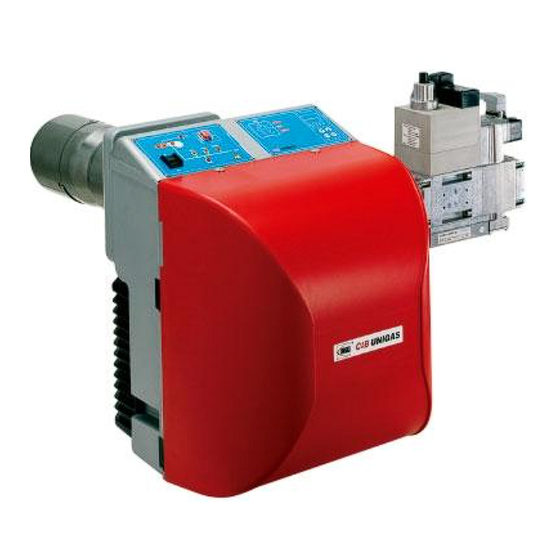
- Page 5 PART I: INSTALLATION PART I: INSTALLATION GENERAL FEATURES The control system is made of the Siemens LMV central unit that performs all the burner control functions and of the Siemens AZL local programming unit that interfaces the system with the user. Fig.
- Page 6 PART I: INSTALLATION How to interpret the burner “Performance curve” To check if the burner is suitable for the boiler to which it must be installled, the following parameters are needed: furnace input, in kW or kcal/h (kW = kcal/h / 860); ...
- Page 7 PART I: INSTALLATION BURNERS SPECIFICATIONS Burner model identification Burners are identified by burner type and model. Burner model identification is described as follows. Type NGX550 Model .* A. NG - Natural gas burner LG - L.P.G. burner (1) BURNER TYPE NGX - Low NOx burners LGX - Natural gas Low NOx burners M - Natural gas...
- Page 8 PART I: INSTALLATION Matching the burner to the boiler The burners described in this manual have been tested with combustion chambers that comply with EN676 regulation and whose dimensions are described in the diagram . In case the burner must be coupled with boilers with a combustion chamber smaller in dia- meter or shorter than those described in the diagram, please contact the supplier, to verify that a correct matching is possible, with respect of the application involved.
- Page 9 Technical Specifications NG550 NG550 NG550 NG550 LG550 LG550 LG550 LG550 BURNERS M-.xx.. M.xx... M.xx... M.xx... L-.xx.. L-.xx... L-.xx... L-.xx... 0.25 0.32 0.40 0.50 0.25 0.32 0.40 0.50 160 - 570 Output min. - max kW Natural gas L.P.G. Fuel Gas category...
- Page 10 PART I: INSTALLATION Performance curves NG550 - LG550 Double-stage/Progressive 100 150 200 250 300 350 400 450 500 550 600 650 NGX550 Low NOx burner To get the input in kcal/h, multiply value in kW by 860. Data are referred to standard conditions: atmospheric pressure at 1013mbar, ambient temperature at 15°C.
- Page 11 PART I: INSTALLATION Pressure in the network/gas rate curves Natural gas burners NG550 Progressive Rp 1" Rp 1"¼ Rp 1"½ (40) Rp 2" (50) Gas rate Stm L.P.G. Burners LG550 Double-stage/Progressive LG550Double-stage/Progressive R p 1" ¼ ( 3 2 ) R p 1"...
- Page 12 Overall dimensions (mm) Standard burners Boiler drilling plate and burner flange Omin ±5mm ±5mm NG/LG550 25/32 843 165 178 384 384 M10 246 NG/LG550 165 178 384 384 M10 246 NG/LG550 165 178 384 384 M10 246 * S = standard blast tube L = extended blast tube...
- Page 13 Low NOx Burner Boiler drilling plate and burner flange Omin Omax ±5mm ±5mm 25/32 874 NGX550-LGX550 * S = standard blast tube L = extended blast tube...
- Page 14 PART I: INSTALLATION MOUNTINGS AND CONNECTIONS Packing urners are despatched in cardboard packages whose dimensions are: 1030mm x 530mm x 570mm (L x P x H) Packing cases of this type are affected by humidity; the maximum number of cases to be stacked is showed outside the packing. The following are placed in each packing case.
- Page 15 PART I: INSTALLATION GAS TRAIN CONNECTIONS This paragraph shows the gas train components which are included in the delivery and those which must be fitted by the customer. The diagram complies with regulations in force ATTENTION: BEFORE EXECUTING THE CONNECTIONS TO THE GAS PIPE NETWORK, BE SURE THAT THE MANUAL CUTOFF VALVES ARE CLOSED.
- Page 16 PART I: INSTALLATION MOUNTING POSITIONS Fig. 5 Fig. 6 Fig. 7 Fig. 8 MULTIBLOC DUNGS MB-DLE 415..420 Mounting 1. Loosen screws A and B do not unscrew (Fig. 5 - Fig. 6). 2. unscrew screws C and D (Fig. 5 - Fig. 6). 3.
- Page 17 PART I: INSTALLATION ELECTRICAL CONNECTIONS Respect the basic safety rules. make sure of the connection to the earthing system. do not reverse the phase and neutral connections. fit a differential thermal magnet switch adequate for connection to the mains. ATTENTION: before executing the electrical connections, pay attention to turn the plant’s switch to OFF and be sure that the burner’s main switch is in 0 position (OFF) too.
- Page 18 PART I: INSTALLATION Fig. 16 - 7-poles and 4-poles connectors Fig. 17 - Electric motor 3-poles connector BURNER IN LOW FLAME SIGNALLING LAMP LOW FLAME TIME METER FAN MOTOR HIGH FLAME TIME METER THERMOSTATS O PRESSURE SWITCHES SERIE FAN MOTOR LINE FUSE HIGH LOW FLAME THERMOSTAT/PRESSURE SWITCH LINE FUSE SAFETY THERMOSTAT/PRESSURE SWITCH...
- Page 19 PART I: INSTALLATION Note on elecrtical supply If the power supply to the burner is 230V three-phase or 230V phase-phase (without a neutral), with the Siemens LMV2... control box, between the terminal 2 on the board and the earth terminal, an RC Siemens RC466890660 filter must be inserted. C - Capacitor (22nF/250V) LME - Siemens control box R - Resistor (1Mohm)
- Page 20 PART I: INSTALLATION User interface User interface The AZL2x.. display is shown below: The AZL2x.. display is shown below: The keys functions are the following: Key F Used to adjust the “fuel” actuator position (Fuel): : While pressing the F key, the “fuel” actuator position can be changed by means of the + and - keys. Key A Used to adjust the “air”...
- Page 21 PART I: INSTALLATION Lock+unlock codes Flame Open valves Ignition transformers energised Fan motor energised Oil pre-heater energised Plant heat request Parametere setting mode Info mode Service mode Closing actuator Opening actuator Unit measure The display will show these data: Setting menu The setting menu is divided into different blocks: Bloc.
- Page 22 PART I: INSTALLATION TSA1= 1st safety time (ignition transformer Ph40 TSA1 = primo tempo sicurezza (trasformatore accensione ON) TSA1 = primo tempo sicurezza (trasformatore accensione OFF) TSA1 = 1st safety time (ignition transformer OFF) Ph42 t42 = preignition time OFF Ph44 t44 = intervallo 1 t44 = interval 1...
- Page 23 PART I: INSTALLATION Info level To enter the Info level, proceed as follows: in any menu position, press keys + and - at the same time, then the program will start again: the display will show OFF. until the display will show InFo, Press the enter (InFo) key then il will show the first code (167) flashing, on the right side it will show the data entered.
- Page 24 PART I: INSTALLATION If a message like the one below is shown during operation, it means that the burner is locked out and the Errore code is shown (in the example “error code:4”); this message is alternating with another message Diagnostic code (in the example “diagnostic code:3”).
- Page 25 PART I: INSTALLATION The service level shows all the information about flame intensity, actuators position, number and lock codes: Parameter Description Flame intensity % output, if set = automatic operation Actuators position, 00=combustibile; 01= aria Lock-outs number 701..725 Lock-outs History (see chapter 23 in the LMV2x manual) .the first parameter will be “954”: the percentage of flame is shown on the right.
- Page 26 PART I: INSTALLATION PHASES LIST During operation, the following program phases are shown. The meaning for each phase is quoted in the table Info levelCombustion head pressure curves vs. the gas flow rate below Curves are referred to pressure= 0mbar in the combustion head! The curves referred to the gas pressure in the combustion head, depending on the gas flow rate, are referred to the burner in the com- bustion stage (percentage of residual O in the flues as shown in the “Recommended combustion values”...
- Page 27 Natural gas flow rate shown in diagram Real gas flow rate Natural gas density shown in diagram Real gas density Gas pressure in combustion head vs. gas flow rate curves NGX550 Gas rate Stm NG550 Gas rate Stm LG550 L.P.G. L.P.G. rate Stm...
- Page 28 PART I: INSTALLATION ATTENTION: before starting the burner up, be sure that the manual cutoff valves are open and check that the pres- sure upstream the gas train complies the value quoted on paragraph “Technical specifications”. Be sure that the mains switch is closed.
- Page 29 PART I: INSTALLATION Startup Output The start-up heat output shall not exceed 120 kW (single stage burners) or 1/3 of nominal output (double-stage, progressive or fully modulating burners). In order to comply with these requirements, burners are provided with butterfly valve and/or slow-opening safety valve.
- Page 30 PART I: INSTALLATION quently the gas rate; screwind VR the rate increases, unscrewing it decreases (see next figure). T(VR) Dungs Multibloc MB-DLE Siemens VGD.. Pressure stabiliser is factory-set. The setting values must be locally adapted to machine conditions. Important! Follow the instruc- tions carefully! Once the curvepoints are set, adjust the pressure switches (see next par.).
- Page 31 PART I: INSTALLATION Adjusting the combustion head The burner is factory-set with the combustion head at the position that refers to the "MAX" output. The maximum output setting refers to the “fully-ahead” position of the combustion head, as far as standard models (Fig. 23), and to “fully-backward” position for low NOx bur- ners (Fig.
- Page 32 PART I: INSTALLATION Calibration of air and gas pressure switches The air pressure switch locks the control box if the air pressure is not the one requested. If it hap- pens, unlock the burner by means of the control box unlock pushbutton, placed on the burner control panel.
- Page 33 PART II: OPERATION PART II: OPERATION LIMITATIONS OF USE THE BURNER IS AN APPLIANCE DESIGNED AND CONSTRUCTED TO OPERATE ONLY AFTER BEING CORRECTLY CONNEC- TED TO A HEAT GENERATOR (E.G. BOILER, HOT AIR GENERATOR, FURNACE, ETC.), ANY OTHER USE IS TO BE CONSIDE- RED IMPROPER AND THEREFORE DANGEROUS.
- Page 34 PART II: OPERATION OPERATION ATTENTION: BEFORE STARTING THE BURNER UP, BE SURE THAT THE MANUAL CUTOFF VALVES ARE OPEN AND CHECK THAT THE PRESSURE VALUE UPSTREAM THE GAS TRAIN MATCHES THE VALUE ON PARAGRAPH “TECHNICAL SPECIFICATIONS”). CHECK THAT THE MAINS SWITCH IS CLOSED. CAREFULLY READ THE “WAR- NINGS”...
- Page 35 PART III: MAINTENANCE PART III: MAINTENANCE At least once a year carry out the maintenance operations listed below. In the case of seasonal servicing, it is recommended to carry out the maintenance at the end of each heating season; in the case of continuous operation the maintenance is carried out every 6 months.
- Page 36 PART III: MAINTENANCE Removing the filter in the MULTIBLOC DUNGS MB-DLE 415 - 420 B01 1” 1/2 - 2” Check the filter at least once a year! Change the filter if the pressure difference between pressure connection 1 and 2 (Fig. 28-Fig. 29) p> 10 mbar. ...
- Page 37 PART III: MAINTENANCE Removing and cleaning the combustion head Remove the 4 screws V1, V2, V3, V4 and the couple of screws S1 and S2 (Fig. 31). ATTENTION: the screw V1 is longer than the other and must be replaced in its seat. Remove the connector CR of the ionization electrode (Fig.
- Page 38 Check the electrodes position after any intervention on the combustion head. The gap between the ignition electrode and the ground is 4 ÷ 5 mm (see Fig. 36). Ground electrode Detection electrode detection electrode NG550 NGX550 Fig. 36...
- Page 39 PART III: MAINTENANCE Checking the detection current figuraTo measure the detection signals refer to the diagrams in the picture below. If the signal is less than the indicated value, check the position of the detection electrode, the electrical contacts and if necessary replace the detection electrode. Minimum Control box detection signal...
- Page 40 BURNER EXPLODED VIEW...
- Page 41 POS. DESCRIPTION POS. DESCRIPTION EXTENDED BLAST TUBE ELASTIC RING GENERATOR GASKET IGNITION TRANSFORMER BURNER HOUSING AIR PRESSURE SWITCH FLANGED PIPE CONTACTOR MOTOR SUPPORT PLATE CONTROL BOX PRESSURE PLUG CONNECTOR FAN WHEEL CONNECTOR MOTOR GAS VALVES GROUP WITH GOVERNOR FAIRLEAD FLANGE COVER FIXING SCREW THREADED GAS PIPE BRACKET...
- Page 42 PART III: MAINTENANCE ELECTRICAL WIRING DIAGRAMS Wiring diagram SE04-755 - Progressive burners Wiring diagram SE04-753 - Fully-modulating burners...
- Page 60 C.I.B. UNIGAS S.p.A. Via L.Galvani, 9 - 35011 Campodarsego (PD) - ITALY Tel. +39 049 9200944 - Fax +39 049 9200945/9201269 web site: www.cibunigas.it - e-mail: cibunigas@cibunigas.it Note: specifications and data subject to change. Errors and omissions excepted.
- Page 61 AZL2x - LMV2x/3x Burner Management System Service manual 03/2023 M12916CD Rev. 3.4...
- Page 62 INDEX MICROPROCESSOR CONTROLLED SYSTEM..........................6 User interface....................................6 Parameters level (heating engineer)............................... 8 Setting menu....................................9 Block 000: Internal Parameter ..............................10 Block 100: General information..............................10 Block 200: Burner control................................13 Block 400: Setting air/fuel ratio curves............................25 Block 500: Air/fuel ratio control ..............................26 Block 600: Actuators ..................................
- Page 63 DANGERS, WARNINGS AND NOTES OF CAUTION THIS MANUAL IS SUPPLIED AS AN INTEGRAL AND ESSENTIAL PART OF THE PRODUCT AND MUST BE DELIVERED TO THE USER. INFORMATION INCLUDED IN THIS SECTION ARE DEDICATED BOTH TO THE USER AND TO PERSONNEL FOLLOWING PRO- DUCT INSTALLATION AND MAINTENANCE.
- Page 64 DIRECTIVES AND STANDARDS do not leave the equipment exposed to weather (rain, sun, etc.) unless expressly required to do so; Gas burners European directives: do not allow children or inexperienced persons to use equipment; - Directive 2009/142/EC - Gas Appliances; The unit input cable shall not be replaced by the user.
- Page 65 -EN 55014-1Electromagnetic compatibility - Requirements for household appliances, electric tools and similar apparatus. -UNI EN 676 (Gas Burners; -CEI EN 60335-1(Household and similar electrical appliances - Safety. Part 1: General requirements; - EN 50165 Electrical equipment of non-electric appliances for household and similar purposes.
- Page 66 MICROPROCESSOR CONTROLLED SYSTEM The control system is made of the Siemens LMV central unit that performs all the burner control functions and of the Siemens AZL local programming unit that interfaces the system with the user. Keys Burner AZL2.. Air actuator Fuel actuator LMV2..
- Page 67 The keys functions are the following: Key F Used to adjust the “fuel” actuator position (Fuel): : While pressing the F key, the “fuel” actuator position can be changed by means of the + and - keys. Key A Used to adjust the “air” actuator position (Air): While pressing the A key, the “air”...
- Page 68 Parameters level (heating engineer)
- Page 69 Setting menu The seeting menu is divided into different blocks: Bloc. Descrizione Description Password Internal parameters OEM / Service Informazioni generali General OEM / Service / Info Controllo bruciatore Burner control OEM / Service Controllo bruciatore (solo LMV26) Burner control (LMV26 only) OEM / Service Curve rapporto Ratio curves...
- Page 70 Block 000: Internal Parameter Param. Descrizione Description Password Password livello assistenza (ingegnere del Password heating engineer (4 characters) calore) Password livello OEM (costruttore del brucia- Password OEM (5 characters) tore) Start backup / restore via AZL2.../ PC sof- tware (set parameter to 1) Index 0: Create backup Index 1: Execute restore Error dia- Start backup/restore via AZL2x/PC gnostics via negative values...
- Page 71 Frequenza di rete Mains frequency 0 = 50 Hz 0 = 50 Hz Service / Info 1 = 60 Hz 1 = 60 Hz Luminosità display Display brightness Service / Info Tempo dopo il quale, se non viene premuto nessun tast il software esce dalla modalita Timeout for menu operation (default value = programmazione (valore fabbrica = 60min - 60min - range: 10 - 120 min)
- Page 72 Numero totale di partenze (non azzerabile) Total number of startups Service / Info Volume combustibile (azzerabile da OEM) Fuel volume (resettable by OEM) Service / Info Fuel 1(secondo combustibile)Ore di eserci- Fuel 1: Operation hours resettable Service / Info zio (azzerabile da Service) Fuel 1 (secondo combustibile) Numero di Fuel 1: Number of startups resettable Service / Info...
- Page 73 Block 200: Burner control Param. Descrizione Description Password Modalità funzionamento bruciatore ( rampa Burner operating mode (fuel train, modula- combustibile, modulante / multistadio, servo- ting / multistage, actuators, etc..) comandi, ecc.) __= non definito (cancellazione curve) __= undefined (delete curves) 1 = accensione diretta a gas (G mod) 1 = gas direct ignition (G mod) 2 = accensione tramite pilota gas con attacco...
- Page 74 15 = gas rampa Gp1 modulante pneumatico 15 = Gp1 mod pneu without actuator senza servomotori (Gp1 mod pneu) 16 = Gp2 mod pneu without actuator 16 = gas rampa Gp2 modulante pneumatico 17 = Lo 2-stage without actuator senza servomotori (Gp2 mod pneu) 18 = Lo 3-stage without actuator 17 = olio LO 2 stadi senza servomotori 19 = G mod gas actuator only...
- Page 75 Gas: sonda rilevazione fiamma attivo (valore Gas: active detector flame evaluation (default fabbrica = 1) value = 1) OEM / Service 0 = QRB../QRC.. 1 = ION / QRA.. Gas: Preventilazione (valore fabbrica = 1) Gas: Pre-purging (default value = 1) 1 = attivo 1 = active 0 = non attivo...
- Page 76 Gas: Pressostato gas di minima (default = 1) Gas: Pressure switch-min input 0 = inattivo 0 = inactive 1 = pressostato gas di minima (a monte val- 1 = pressure switch-min (upstream of fuel vola V1) valve 1 (V1)) 2 = controllo perditavalvole via pressostato 2 = valve proving via pressure switch-min OEM / Service (montato tra le valvole V1 e V2)
- Page 77 Gas: tempo pressione atmosferica controllo Gas: proving test time atmospheric pres- tenuta (valore fabbrica = 10s - range impo- sure (default value = 10s - range:0.2s - 60s) stazione:0.2s - 60s) Gas: tempo riempimento controllo tenuta Gas: proving test filling time (default value = (valore fabbrica = 3s - range imposta- 3s - range:0.2s - 10s) zione:0.2s - 10s)
- Page 78 Olio: Intervallo 1 (valore fabbrica = 2s - Oil: Interval 1 (default value = 2s - OEM / Service range impostazione:0.2s - 60min) range:0.2s - 60min) Olio: tempo di sicurezza 2 (TSA2) (valore Oil: safety time 2 (TSA2) (default value = 3s fabbrica = 3s - range impostazione:0.2 - 10s) - range:0.2 - 10s) Olio: Intervallo 2 (valore fabbrica = 2s -...
- Page 79 Block 300: Burner control (only with LMV26) Param. Descrizione Description Password Combustibile 1 : Modalità funzionamento bru- Fuel 1 : Burner operating mode (fuel train, ciatore ( rampa combustibile, modulante / modulating / multistage, actuators, etc..) multistadio, servocomandi, ecc.) __= non definito (cancellazione curve) __= undefined (delete curves) 1 = accensione diretta a gas (G mod) 1 = gas direct ignition (G mod)
- Page 80 11 = olio 2 stadi con accensione tramite pilota 11 = LoGp 2-stage (LOGp 2-stage) 12 = Lo mod 2 fuel valves 12 = olio modulante con 2 valvole combusti- 13 = LoGp mod 2 fuel valves bile (LOmod 2 valvole) 14 = G mod pneu without actuator 13 = olio modulante con 2 valvole combusti- 15 = Gp1 mod pneu without actuator...
- Page 81 Combustibile 1 - Gas: tempo di preaccen- Fuel 1 - Gas: Preignition time (default value = sione (valore fabbrica = 2s - range imposta- 2s - range: 0.2s - 60min) OEM / Service zione:0.2s - 60min) Combustibile 1 - Gas: tempo di sicurezza 1 Fuel 1 - Gas: Safety time 1 (TSA1) (default (TSA1) (valore fabbrica = 3s - range impo- value = 3s - range: 0.2 - 10s)
- Page 82 Limite ripetizioni perdita di fiamma (valore Repetition limit loss of flame (default value= 2 fabbrica = 2 - range impostazione:1 - 2) - range:1 - 2) Fuel 1 - Gas: execution proving test (default Combustibile 1 - Gas: esecuzione controllo value= 2) tenuta (valore fabbrica = 2) 0 = no controllo tenuta...
- Page 83 Fuel 1 - Oil: prepurging (default value = 1) Combustibile 1 - Olio: preventilazione (valore fabbrica = 1) 0 = deactivated 1 = attivo 1 = activated 0 = non attivo 0 = deactivated OEM / Service In ambito civile la norma EN267 rende obbli- WARNING: in the civil field, the prepurge is gatoria la preventilazione.
- Page 84 Limite ripetizioni perdita di fiamma (valore Repetition limit value loss of flame (default fabbrica = 2 - range impostazione:1 - 2) value = 2 - range:1 - 2) Fuel 1 - Oil: time oil ignition (default value = Combustibile 1 - Olio: tempo iniezione olio (valore fabbr.
- Page 85 Block 400: Setting air/fuel ratio curves Param. Descrizione Description Password Curve controllo servocomando combustibile Ratio control curve fuel actuator (F): it acces- (F): si accede alla lista dei punti da impostare ses to the parameter list of the points to be set OEM / Service (da P0 a P9) - consultare paragrafo “Imposta- (P0 to P9) - see paragrapf “Setting the curves”...
- Page 86 Block 500: Air/fuel ratio control Param. Descrizione Description Password No-flame position fuel actuator Posizione servocomando combustibile in assenza di fiamma (no-flame) Indice 0 = posizione di sosta = 0° Index 0 = no-load position = 0° OEM / Service Indice 1 = posizione preventilazione = 0° Index 1 = prepurge position = 0°...
- Page 87 Activation of VSD / PWM fan (PWM = Pulse- Width Modulation) Activation of VSD / PWM fan OEM / Service 0=deactived 1=actived (PWM = Pulse-Width Modulation) Parameter 544 Modulation Modulation Modulation Modulation Actuator Actuating speed param- Max. delta between the curve points eter 613 OEM / Service Actuator...
- Page 88 Block 600: Actuators Param. Descrizione Description Password Impostazione punto di riferimento Selection of reference point Indice 0 = combustibile Index 0 = fuel Indice 1 = aria Index 1 = air 0 = chiuso (<0°) 0 = closed (<0°) 1 = aperto (>90°) 1 = open (>90°) Direzione rotazione del servocomando Actuator’s direction of rotation...
- Page 89 Tipo di riferimento dei servocomandi index 0 = fuel (default = 0 (riferimento stan- dard) Type of referencing index 1 = air (default = 0 (riferimento stan- Index 0 = fuel dard) Index 1 = air 0 = standard 0 = standard 1 = fermo entro il raggio utile 1 = stop within usable range 2 = fermi interni (SQN1...)
- Page 90 Configurazione uscita analogica % di carico Configuration of analog output (default value (valore fabbrica = 0) = 0) 0 = DC 0..10 V 0 = DC 0..10 V OEM / Service 1 = DC 2..10 V 1 = DC 2..10 V 2 = DC 0/2..10 V 2 = DC 0/2..10 V ATTENTION: as for SQM3x actuators, set the direction according to the acutator function.
- Page 91 Block 700: Error history Param. Descrizione Description Password Storico errori: 701 - 725.01.codice Error history: 701 - 725.01.code Service / Info Storico errori: 701 - 725.02.codice diagnostico Error history: 701 - 725.02.diagnostic code ° Service / Info Storico errori: 701 - 725.03.classe errore Error history: 701 - 725.03.error class °...
- Page 92 Block 900: Process data Param. Descrizione Description Password Potenza attuale (valore fabbrica = 0% - range Current output (default value = 0% - range = impostazione = 0-100%) 0-100%) Service / Info Indice 0 = combustibile Index 0 = fuel Indice 1 = aria Index 1 = air Posizione incrementale servocomandi (valore...
- Page 93 Actuators references An incremental transducer is used to ensure position feedback. Referencing of the actuators must be performed after power-on. In addition, at the end of each shutdown in phase 10, the actuators are referenced to ensure that individual stepping errors, which could lead to shutdown, do not accumulate.
- Page 94 COMMISSIONING THE BURNER The LMV2x complete programming must be performed on units that has never been set before or reset units (e.g. spare parts). The programming procedure is performed by setting the following main parameters: if LMV.. is a spare part, insert burner ID (parameter 113) at least 4 digit. type of fuel train (parameter “201”) air/fuel ratio curvepoints (Block “400”) maximum load percentage (parameter “546”)
- Page 95 the types of fuel trains are the following: Param. Descrizione Description Password Modalità funzionamento bruciatore ( rampa Burner operating mode (fuel train, mod / multi- comb., mod. / multistadio, servocom., ecc.) stage, actuators, etc.) __= non definito (cancellazione curve)___= __= undefined (delete curves) 1 = accensione diretta a gas (G mod) 1 = gas direct ignition(G mod) 2 = accensione tramite pilota gas con attacco...
- Page 96 Lo 3-stage In the example the Gmod gas train has been set (Configuration “1”). Choose the fuel train by pressing ENTER, then press “+” / “-”. Press ENTER to confirm: number “1” will appear on the right side of the display.
- Page 97 CAUTION: at the first burner adjustment, it is recommended to set the maximum output P9 at the same value (or little higher) of the ignition point, in order to safely reach point P9 next (see next paragraph). By pressing “+” the display will show: The burner is ready to startup.
- Page 98 Warm setting Once pressed button “enter” and the chain thermostats open (X5-03 terminals), the LMV.. show Ph12.Then close the chain termostat and the unit performs the prepurge cycle (see “Phases List”) and stops at the ignition point P0 without ignition anyway. By pressing “+”, the burners lights abd the air/fuel ratio can be properly set in presence of flame.
- Page 99 P5, keep pressing “-” unitl “Calc” is displayed. The curve will be processed again downwards point P1. Fuel deviation between two following points: 25°max. 12 press “-” to go through the lower points and check the combustion values, if necessary change the points as described above. 13 By pressing ESC, at the end of the points adjusments, the parameter “546”...
- Page 100 BURNER STARTUP WITH LMV2x ALREADY PROGRAMMED Once the LMV turns on, the AZL display will show The burners is basically factory set. The air/fuel ratio curve is set with the maximum output point P9 a little higher or equal to P0. To adjust the burner on the plant site, adjust the maximum output point to the flow rate values really requested.
- Page 101 Set the air/fuel ratio curvepoints as described on chapter “Programming the LMV2x” Note: the other phases are Ph60 = operation (OP= in modulation) Ph62 = travelling to shutdown Ph70 = off but in prepurge after the burntime Ph72 = travelling to postpurging Ph74 = postpurge (countdown is displayed) Press ESC the parameter “546”...
- Page 102 Reset / manual lockout The system can be manually locked by simultaneously pressing the ENTER (InFo) button and any other button on the AZL2..This function allows the user to stop the system from the operating level should an emergency occur. When making a reset, the following actions are carried out: Alarm relay and the fault display are off ...
- Page 103 Entering the Parameter levels By means of a proper use of the keys, it is possible to enter the various level parameters, as shown in the following flow chart: The burner and consequently the LMV2x.. are factory set; the air and fuel curves as set as well.
- Page 104 Info level To enter the Info level, proceed as follows: in any menu position, press keys + and - at the same time, then the program will start again: the display will show OFF. , until the display will show InFo, Press the enter (InFo) key then il will show the first code (167) flashing, on the right side it will show the data entered.
- Page 105 10 Press InFo for more than three seconds or for more than three seconds orto return to the normal display. If a message like the one below is shown during operation, it means that the burner is locked out and the Errore code is shown (in the example “error code:4”); this message is alternating with another message Diagnostic code (in the example “diagnostic code:3”).
- Page 106 Service level To enter the Service mode, press InFo until the display will show: The service level shows all the information about flame intensity, actuators position, number and lock codes: Parameter Description Flame intensity % output, if set = automatic operation Actuators position, 00=combustibile;...
- Page 107 PHASES LIST Fase /Phase Funzione Function Ph00 Fase blocco Lockout phase Ph01 Fase di sicurezza Safety phase Ph10 t10 = tempo raggiungimento posizione riposo t10 = home run Ph12 Pausa Standby (stationary) t22 = tempo di salita ventilatore (motore ventilatore t22 = fan ramp up time (fan motor = ON, safety Ph22 = ON, valvola intercettazione di sicurezza = ON)
- Page 108 BACKUP PARAMETER WITH AZL2x On the AZL2x you can save the configuration to download on another appliance LMV. To do this: access up, press F and A at the same time enter the password following the procedure on chapter “Programming LMV2x”. Press ENTER until the display will show: with the button go to the group 000 of the parameters and press...
- Page 109 RESTORE PARAMETER FROM AZL2x TO LMV.. To copy the previously saved configuration on AZL2x proceed as follows: access up, press F and A at the same time enter the password following the procedure on chapter “Programming LMV2x”. Press ENTER until the display will show: To copy the configuration from AZL2x to LMV.
- Page 110 ERROR CODE TABLE...
- Page 125 WIRING DIAGRAM Wiring connection for LMV20 Electrical supply Burner flange Fanmotor input Safety loop Lokout signal Continuous fan operator Valve External valveSV gnition transformer Valve Operation sgnal Reset Reserve Common Increase output Pressure switch leakage test Decrease input gasPGCP ON/OFF thermosta Minimum gas pressure switch Air pressure switch LUFT...
- Page 126 Wiring variants for LMV27 ConnectorX75 2 - Fuel meter input 1 - Supply fuel meter ConnectorX5-02 ConnectionsPmax...
- Page 127 Wiring variants for LMV26 ConnectorX08-04 / X09-04 2 - Fuel 0 1 - Fuel1 ConnectorX75 2 - Fuel meter input 1 - Supply fuel meter ConnectorX64 5 -Power supply speed sensor 4 -Speed sensor input 3 - PWM (Pulse Width Modulation) speed output 2 - GND (signal reference) 1 -Controller input (4÷20mA) ConnectorX74...
- Page 128 Wiring variants for LMV37 ConnectorX75 2 - Fuel meter input 1 - Supply fuel meter ConnectorX5-02 Connections Pmax ConnectorX64 5 -Power supply speed sensor 4 -Speed sensor input 3 - PWM (Pulse Width Modulation) speed output 2 - GND (signal reference) 1 -Controller input (4÷20mA) ConnectorX74 5 -Supply...
- Page 132 C.I.B. UNIGAS S.p.A. Via L.Galvani, 9 - 35011 Campodarsego (PD) - ITALY Tel. +39 049 9200944 - Fax +39 049 9200945/9201269 web site: www.cibunigas.it - e-mail: cibunigas@cibunigas.it Note: Specifications and and data subject to change. Errors and omissions excepted.
- Page 133 CIB UNIGAS 600V CONTROLLER USER’S MANUAL COD. M12925CA Rel 1.2 08/2014 SOFTWARE VERSION 1.0x code 80379 / Edition 01 - 06/2012 1 • INSTALLATION 2 • TECHNICAL SPECIFICATIONS Display 2x4 digit green, high display 10 and 7mm Keys 4 of mechanical type (Man/Aut, INC, DEC, F) •...
- Page 134 3 • DESCRIPTION OF FACEPLATE Function indicators Indication of output states Indicates modes of operation OUT 1 (AL1); OUT 2 (OPEN); OUT 3 (CLOSED) MAN/AUTO = OFF (automatic control) ON (manual control) PV Display: Indication of process variable Error Indication: LO, HI, Sbr, Err PRE-HEATING = ON (running) LO= the value of process variable is <...
- Page 135 5 • “EASY” PROGRAMMING and CONFIGURATION S4 Jumper THE EASY CONFIGURATION (Pro=0...12) IS SUITABLE FOR (CPU) VERSIONS WITH AL1/OPEN/CLOSED LEVEL 1 MENU P.V. / S.V. Process variable P.V. / S.V. (PV display) Work Setpoint (SV display) or control output value with controller in manual Password Local Setpoint...
- Page 136 • InFo Display Information display Software version 0 No Error Self diagnostic 1 Lo error code 2 Hi 3 ERR 4 SBR OUTPUT 2 OUTPUT 3 SERIAL COMMUNICATION 0 = None 0 = None 0 = None +8 error OUT2 card recognition 1 = Relay 1 = Relay +16 error OUT3 card recognition...
- Page 137 • InP Input settings S, R range 0...1750°C; error < 0.2% f.s. (t > 300°C) / for other sp. r 0 default (remote setpoint present) Def. remote setpoint range; error < 0.5% f.s. error < 0.2% f.s. (t > -150°C) range 44...1800°C;...
- Page 138 • Out Output settings Select a1. r reference signal for alarm1 AL.1.r AL.x.r Variable to be compared PV (process variable) AL.1.t AL.x.t Direct (high limit) Absolute or Normal 2/3 for a1. t Inverse (low limit) relative to Symmetrical alarm 1 active setpoint (window) direct...
- Page 139 • Prot Protection code Prot Display Modification SP, Hy.P, Hy.n, AL.2, AL.3, PoS, OuP, INF SP, Hy.P , Hy.n, AL.2, AL.3, PoS SP, Hy.P, Hy.n, AL.2, AL.3, PoS, OuP, INF SP, OuP, INF + 4 to disable InP, Out + 8 to disable CFG + 16 to disable SW “power-up - power down”...
- Page 140 ld. 1 Function of LEDs Val. Function none MAN/AUTO controller ld. 2 HOLD Selftuning enabled Autotuning enabled ld. 3 Error present Softstart running Set point gradient running Pre-heating running + 16 LED flashes if active • Lin Custom linearization for main input Step 0 beginning Display limits s.
- Page 141 7 • CONSENT FOR BURNER AL1 Obtain burner consent by configuring alarm 1 as inverse deviation with positive hysteresis Hy.P and negative hysteresis Hy.n 8 • PRE-HEATING FUNCTION Enable the pre-heating function by setting parameters GS.0, Ht.0, GS.1 other than zero. It consists of three phases that are activated sequentially at firing: - Ramp 0 phase Enabled by setting GS.0 >...
- Page 142 9 • ADJUSTMENT WITH MOTORIZED VALVE In an adjustment process the adjustment valve has the function of varying fuel delivery (frequently corresponding to the thermal energy introduced into the process) in relation to the signal coming from the controller. For this purpose it is provided with an actuator able to modify its opening value, overcoming the resistances produced by the fluid passing inside it.
- Page 143 Valve control modes With the controller in manual, the setting of parameter At.y ≥ 8 allows direct control of the valve open and close commands through the keyboard Increments and Decrements on the front seats. V0 - for floating valve without potentiometer Model V0 have similar behaviour: every manoeuvre request greater than the minimum impulse t.Lo is sent to the actuator by means of the OPEN/CLOSE relays;...
- Page 144 11 • MANUAL TUNING A) Enter the setpoint at its working value. B) Set the proportional band at 0.1% (with on-off type setting). C) Switch to automatic and observe the behavior of the variable. It will be similar to that in the figure: Process D) The PID parameters are calculated s follows: Proportional band Variable...
- Page 145 15 • ACCESSORIES • Interface for instrument configuration Kit for PC via the USB port (Windows environment) for GEFRAN instruments configuration: KIT PC USB / RS485 o TTL Lets you read or write all of the parameters • A single software for all models •...
- Page 147 21/06/2012 rev. 0 Set-up for 600V RRR0-1-T73 regulator Set up for temperature probe Pt100 (ex Siemens QAE2120 130°C max.) The regulator comes out of the factory preset with the corresponding values of the Siemens RWF40.000 and RWF50.2x Verify wiring of the sensor Regulation of the set-point = 80 It can be modified by using arrows "up"...
- Page 148 A1.r … A1.t 3 (operating mode AL1 =inverse-relative-normal) … rL.1 2 (AL1) rL.2 18 (open) rL.3 19 (close) A.ty 9 (type of servocontrol command) Ac.t 12 (servocontrol running time: SQN72.4…/STA12..=12; SQM40.265=30) t_Lo t_Hi t.on t.oF dE.b 0,1 (dead zone in % of end scale) 99 then push and keep pushed F until visualization of Hrd …...
- Page 149 Set up for temperature probe Pt100 for high temperature (350°C max.) Verify wiring of the sensor Regulation of the set-point = 80 It can be modified by using arrows "up" and "down". By pushing F you go to parameters: Hy.P 10 (hysteresis positive for output 1 terminals 21-22 (ex Q13-Q14) Hy.n -5 (hysteresis negative for output 1 terminals 21-22 (ex Q13-Q14)
- Page 150 A1.r … A1.t 3 (mode AL1 =inverse-relative-normal) … rL.1 2 (AL1) rL.2 18 (open) rL.3 19 (close) A.ty 9 (type of servocontrol command) Ac.t 12 (servocontrol running time: SQN72.4…/STA12..=12; SQM40.265=30) t_Lo t_Hi t.on t.oF dE.b 0,1 (dead zone in % of end scale) 99 then push and keep pushed F until visualization of Hrd …...
- Page 151 Set up for pressure transmitter 2 wires signal 4÷20mA With pressure transmitters first we need to enable their power supply: remove the part as shown below, then, on the CPU unit, move the bridge from Pt100 to +Vt IN/OUT cards Signal selection on terminal 3 Verify wiring of the sensor...
- Page 152 …. 44 (4÷20mA) … dP_S 2 (decimals num.) Transmitter 1,6bar 3bar 10bar 16bar 25bar 40bar Lo.S 0,00 0,00 0,00 0,00 0,00 0,00 min. sensor scale Hi.S 1,60 3,00 10,00 16,00 25,00 40,00 max sensor scale offset of input correction Lo.L 0,00 0,00 0,00...
- Page 153 Set -up for thermocouples type Verify wiring of the sensor Regulation of the set-point = 80 It can be modified by using arrows "up" and "down". By pushing F you go to parameters: Hy.P 10 (hysteresis positive for output 1 terminals 21-22 (ex Q13-Q14) Hy.n -5 (hysteresis negative for output 1 terminals 21-22 (ex Q13-Q14) Keep pushing F until you see PASS, release F and through the arrows set 99, push F and visualize Pro...
- Page 154 A1.r … A1.t 3 (mode AL1 =inverse-relative-normal) … rL.1 2 (AL1) rL.2 18 (open) rL.3 19 (close) A.ty 9 (type of servocontrol command) Ac.t 12 (servocontrol running time: SQN72.4…/STA12..=12; SQM40.265=30) t_Lo t_Hi t.on t.oF dE.b 0,1 (dead zone in % of end scale) 99 then push and keep pushed F until visualization of Hrd …...
- Page 157 RWF50.2x & RWF50.3x User manual M12922CB Rel.1.0 05/2024...
- Page 158 DEVICE INSTALLATION Install the device using the relevant tools as shown in the figure. To wire the device and sensors, follow the instructions on the burner wiring diagram.
- Page 159 FRONT PANEL NAVIGATION MENU Parameter level Basic display User Level - Opr SP1 or SP2 (editable) dSP readable and editable through bin1 = 2 InP1 or y (only display) Parameter Level - PArA HYS1 , HYS2 , HYS3 Pb1, dt, rt, db, tt Next parameter Main navigation...
- Page 160 RWF5 is preset good for 90% of applications. However, you can set or edit parameters as follow: Set-point: set or modification: When the burner is in stand-by, (safety loop open, that is terminals 3-4/T1-T2 on the 7 pole plug open) push the Enter button: on the lower display (green) Opr appears;...
- Page 161 Setting the kind of sensor to be connected to the device: push the Enter button: on the lower display (green) Opr appears. Using the up and down arrows find ConF. Push Enter to confirm. Now on the green display the group InP appears. Push Enter and InP1 is displaied. Enter to confirm. ...
- Page 162 ConF > Cntr Parameter Value Description CtYP 1 = 3-position controller (open-stop-close only RWF50.2) controller type 2 = continuative action controller (only RWF50.3) CACt 1 = heating controller control action 0 = cooling controller least value of the set-point limitation prevents entry of values outside the defined set-point range -1999..0..+9999 range...
- Page 163 ConF > OutP (parameter under group only for RWF50.3) Parameter Value Description FnCt 1 = analog input 1 doubling with possibility to convert tipo di controllo (depending on par SiGn) 4 = modulation controller SiGn physical output signal (terminals A+, A-) type of output signal 0 = 0÷20mA 1 = 4÷20mA...
- Page 164 Manual control : in order to manual change the burner load, while firing keep pushing the ESC button for more than 5 s; on the lower green display Hand appears. using the UP and DOWN arrows, the load varies. ...
- Page 165 Electric connection : With 7 pins connector version With terminals version Matches terminals between RWF50.2 and RWF40.0x0...
- Page 166 Parameters summarising for RWF50.2x: Conf Conf Navigation menù Inp1 Cntr diSP Types of probe SEn1 OFF1 Unit dECP Pb. 1 dt HYS1 (*) HYS3 (*) SP1 (*) Siemens QAE2120… needless needless 80 350 (#) 80 °C Siemens QAM2120.. needless needless 80 350 (#) -2.5 40°C...
- Page 167 APPENDIX: PROBES CONNECTION To assure the utmost comfort, the control system needs reliable information, which can be obtained provided the sensors have been installed correctly. Sensors measure and transmit all variations encountered at their location. Measurement is taken based on design features (time constant) and according to specific operating conditions.With wiring run in raceways, the sheath (or pipe) containing the wires must be plugged at the sensor's terminal board so that currents of air cannot affect the sensor's measurements.
- Page 168 Duct or pipe sensors Installing pressure sensors A - installation on ducts carrying fluids at max. temperature 80°C Installing temperature sensors For measuring outlet air: B - installation on ducts at temperature over 80°C and for refrigerants after delivery fan or C - installation on ducts at high temperatures: ...
- Page 169 Immersion or strap-on sensors Immersion probes installation Sensors must be installed on the stretch of pipe in which fluid circulates all the time. The rigid stem (sensing element doing the measuring) must be inserted by at least 75mm and must face the direction of flow. Recommended locations: on a bend or on a straight stretch of pipe but tilted by 45°...
- Page 170 Duct pressure switches and sensors Installing differential pressure probes for air Basic principles Measuring static pressure(i.e. pressure exerted by air on pipe walls) A - Control a filter (clogging) Measuring dinamic pressure B - Control a fan (upstream/downstream) Kg/m , specific weight of air m/s, air speed 9.81 m/s gravity acceleration...
- Page 171 Spare parts Description Modulator RWF50.2 (uscita a 3 punti - apri, fermo, chiudi) 2570148 2570148 Modulator RWF50.3 (uscita continua 0÷20mA, 4÷20mA, 0÷10V) 2570149 2570149 Temperature probe Siemens QAE2120.010A (30÷130°C) 2560101 2560101 2560135 Temperature probe Siemens QAM2120.040 (-15÷+50°C) 2560135 Thermoresistor Pt1000 ø6mm L100mm (30÷130°C) 2560188 2560188 2560103 Thermoresistor Pt1000 ø10mm L200mm (0÷350°C) 2560103...
- Page 172 Note: Specifications and data subject to change. Errors and omissions excepted.
- Page 173 KM3 Modulator USER MANUAL M12927CA Rel.1.0 10/2020...
- Page 174 M12927CA MOUNTING...
- Page 175 M12927CA DISPLAY Y AND KEY onsent to the burner is rned off OUTP UT LEDs ON (o out1) - Consen nt to the burne ▲ - (o out2) Output i ncrease ▼ - (o out3) Output d decrease ● - (ou ut4) Modulato r is powered o perator Mode...
- Page 176 M12927CA CONNECTIONS DIAGRAM Probe connection: • PT1000/NTC/PTC: between terminal 3 and 2 • PT 100: between terminal 3 and 2 with terminal 1 • Passive pressure probe 0/4-20 mA: between terminal 4 ( + ) e 1 ( - ) Note: out4 must be activated ( IO4F must be setted to ON ) •...
- Page 177 M12927CA SETPOINT AND HYSTERESIS CONFIGURATION (SP, AL1, HAL1 parameters) Push the button to enter into the setpoint configuration: SP setpoint value change: increase decrease 2480 Confirm / Next AL1 parameter value change: increase decrease Confirm / Next HAL1 HAL1 parameter value change: increase decrease Confirm / Next Back to the first parameter To return to normal mode, press the key for 3 seconds or wait the 10s timeout...
- Page 178 M12927CA LIMITED ACCESS LEVEL Proceed as follows to change some parameters that are not visible in standard user mode: Press the key for Password = 20 3 seconds Access to parameter: Increase the displayed value Decrease the displayed value Confirm and go to next parameter Param Description...
- Page 179 M12927CA...
- Page 180 M12927CA CONFIGURATION How to access configuration level The configuration parameters are collected in various groups. Every group defines all parameters related with a specific function (e.g.: control, alarms, output functions). Push the button for more than 5 seconds. The upper display will show PASS while the lower display will show 0.
- Page 181 M12927CA Safety output value -100... 100 io4.F I/O4 function selection on = Out4 will be ever ON (used as a transmitter power supply) ,out4 = Uscita 4 (Used as digital output 4), dG2c = Digital input 2 for contact closure, dG2U = Digital input 2 driven by 12... 24 diF1 Digital input 1 function oFF = Not used,...
- Page 182 M12927CA windows SE.br = Sensor Break LodE = Deviation low alarm (relative) HidE = Deviation high alarm (relative) LHdo = Relative band alarm in alarm out of the band LHdi = Relative band alarm in alarm inside the band Alarm 1 function 0...
- Page 183 M12927CA AL3 Group - alarm 3 parameters Param Description Values Liv N° Default AL3t Alarm 3 type nonE = Alarm not used nonE LoAb = Absolute low alarm HiAb = Absolute high alarm LHAo = Windows alarm in alarm outside the windows LHAI = Windows alarm in alarm inside the windows...
- Page 184 M12927CA SELF Self tuning enabling no = The instrument does not perform the self- tuning YES = The instrument is performing the self- tuning Proportional band 1... 9999 (E.U.) page 7 Integral time 0 (oFF) ... 9999 (s) page 7 Derivative time 0 (oFF) ...
- Page 185 M12927CA AAc = Alarm reset ASi = Alarm acknowledge chSP = Sequential set point selection St.by = Stand by mode. The first press puts the instrument in stand by mode while a second one puts the instrument in Auto mode. Str.t = Timer run/hold/reset P.run = Program run P.rES = Program reset...
- Page 186 M12927CA con Group - Consumption parameters Param Description Values N° Default Co.tY Count type oFF = Not used 1 = Instantaneous power (kW) 2 = Power consumption (kW/h) 3 = Energy used during program execution. This measure starts from zero when a program runs end stops at the end of the program.
- Page 187 M12927CA OPERATIVE MODES When the instrument is powered, it starts immediately to work according to the parameters values loaded in its memory. The instrument behaviour and its performance are governed by the value of the stored parameters. At power ON the instrument can start in one of the following mode depending on its configuration: Automatic Mode In Automatic mode the instrument drives automatically the control output according to the parameter value set and the set point/measured value.
- Page 188 M12927CA Direct set point modification This function allows to modify rapidly the set point value selected by [83] A.SP (selection of the active Set point) or to the set point of the segment group (of the programmer) currently in progress. Push button.
- Page 189 M12927CA ERROR MESSAGES The upper display shows the OVER-RANGE and UNDERRANGE conditions with the following indications: Over-range: Under-range The sensor break will be signalled as an out of range: Note: When an over-range or an under-range is detected, the alarms operate as in presence of the maximum or the minimum measurable value respectively.
- Page 190 KM3 Modulator USER MANUAL M12927CA Rel.1.0 10/2020...
- Page 191 M12927CA MOUNTING...
- Page 192 M12927CA DISPLAY Y AND KEY onsent to the burner is rned off OUTP UT LEDs ON (o out1) - Consen nt to the burne ▲ - (o out2) Output i ncrease ▼ - (o out3) Output d decrease ● - (ou ut4) Modulato r is powered o perator Mode...
- Page 193 M12927CA CONNECTIONS DIAGRAM Probe connection: • PT1000/NTC/PTC: between terminal 3 and 2 • PT 100: between terminal 3 and 2 with terminal 1 • Passive pressure probe 0/4-20 mA: between terminal 4 ( + ) e 1 ( - ) Note: out4 must be activated ( IO4F must be setted to ON ) •...
- Page 194 M12927CA SETPOINT AND HYSTERESIS CONFIGURATION (SP, AL1, HAL1 parameters) Push the button to enter into the setpoint configuration: SP setpoint value change: increase decrease 2480 Confirm / Next AL1 parameter value change: increase decrease Confirm / Next HAL1 HAL1 parameter value change: increase decrease Confirm / Next Back to the first parameter To return to normal mode, press the key for 3 seconds or wait the 10s timeout...
- Page 195 M12927CA LIMITED ACCESS LEVEL Proceed as follows to change some parameters that are not visible in standard user mode: Press the key for Password = 20 3 seconds Access to parameter: Increase the displayed value Decrease the displayed value Confirm and go to next parameter Param Description...
- Page 196 M12927CA...
- Page 197 M12927CA CONFIGURATION How to access configuration level The configuration parameters are collected in various groups. Every group defines all parameters related with a specific function (e.g.: control, alarms, output functions). Push the button for more than 5 seconds. The upper display will show PASS while the lower display will show 0.
- Page 198 M12927CA Safety output value -100... 100 io4.F I/O4 function selection on = Out4 will be ever ON (used as a transmitter power supply) ,out4 = Uscita 4 (Used as digital output 4), dG2c = Digital input 2 for contact closure, dG2U = Digital input 2 driven by 12... 24 diF1 Digital input 1 function oFF = Not used,...
- Page 199 M12927CA windows SE.br = Sensor Break LodE = Deviation low alarm (relative) HidE = Deviation high alarm (relative) LHdo = Relative band alarm in alarm out of the band LHdi = Relative band alarm in alarm inside the band Alarm 1 function 0...
- Page 200 M12927CA AL3 Group - alarm 3 parameters Param Description Values Liv N° Default AL3t Alarm 3 type nonE = Alarm not used nonE LoAb = Absolute low alarm HiAb = Absolute high alarm LHAo = Windows alarm in alarm outside the windows LHAI = Windows alarm in alarm inside the windows...
- Page 201 M12927CA SELF Self tuning enabling no = The instrument does not perform the self- tuning YES = The instrument is performing the self- tuning Proportional band 1... 9999 (E.U.) page 7 Integral time 0 (oFF) ... 9999 (s) page 7 Derivative time 0 (oFF) ...
- Page 202 M12927CA AAc = Alarm reset ASi = Alarm acknowledge chSP = Sequential set point selection St.by = Stand by mode. The first press puts the instrument in stand by mode while a second one puts the instrument in Auto mode. Str.t = Timer run/hold/reset P.run = Program run P.rES = Program reset...
- Page 203 M12927CA con Group - Consumption parameters Param Description Values N° Default Co.tY Count type oFF = Not used 1 = Instantaneous power (kW) 2 = Power consumption (kW/h) 3 = Energy used during program execution. This measure starts from zero when a program runs end stops at the end of the program.
- Page 204 M12927CA OPERATIVE MODES When the instrument is powered, it starts immediately to work according to the parameters values loaded in its memory. The instrument behaviour and its performance are governed by the value of the stored parameters. At power ON the instrument can start in one of the following mode depending on its configuration: Automatic Mode In Automatic mode the instrument drives automatically the control output according to the parameter value set and the set point/measured value.
- Page 205 M12927CA Direct set point modification This function allows to modify rapidly the set point value selected by [83] A.SP (selection of the active Set point) or to the set point of the segment group (of the programmer) currently in progress. Push button.
- Page 206 M12927CA ERROR MESSAGES The upper display shows the OVER-RANGE and UNDERRANGE conditions with the following indications: Over-range: Under-range The sensor break will be signalled as an out of range: Note: When an over-range or an under-range is detected, the alarms operate as in presence of the maximum or the minimum measurable value respectively.
Need help?
Do you have a question about the NG550 and is the answer not in the manual?
Questions and answers