Table of Contents
Advertisement
Quick Links
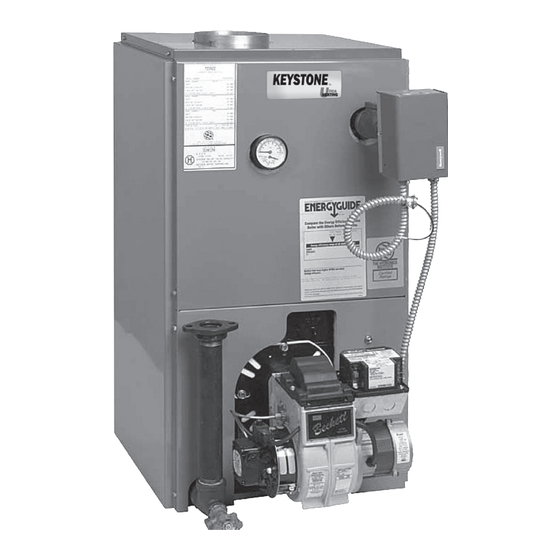
OIL-FIRED
CAST IRON HOT WATER Boiler
INSTALLATION, OPERATION &
MAINTENANCE MANUAL
Utica Heating
2210 Dwyer Avenue, Utica NY 13504-4729
Phone: (315) 797-1310 • Fax: (866) 432-7329
e-mail: info@ecrinternational.com
web site: www.ecrinternational.com
P/N# 1305007UH, Rev. A [02/2011]
An ISO 9001-2008 Certified Company
Advertisement
Table of Contents

Related Manuals for ECR International UTICA HEATING KEYSTONE UH3KW0.60


Summary of Contents for ECR International UTICA HEATING KEYSTONE UH3KW0.60
- Page 1 OIL-FIRED CAST IRON HOT WATER Boiler INSTALLATION, OPERATION & MAINTENANCE MANUAL Utica Heating 2210 Dwyer Avenue, Utica NY 13504-4729 Phone: (315) 797-1310 • Fax: (866) 432-7329 e-mail: info@ecrinternational.com web site: www.ecrinternational.com P/N# 1305007UH, Rev. A [02/2011] An ISO 9001-2008 Certified Company...
- Page 2 OIL-FIRED CAST IRON HOT WATER BOILER Model No. UH3KW0.60 UH3KW0.75 UH3KW1.00 UH4KW0.90 UH4KW1.25 UH4KW1.50 UH5KW1.20 UH5KW1.75 UH5KW2.00 These instructions must be affixed on or adjacent to the boiler. OiL FiReD BOiLeRS These boilers are low pressure, sectional cast iron boilers constructed and hydrostatically tested for a maximum working pressure of 50 psi in accordance with A.S.M.E.
-
Page 3: Table Of Contents
Table of ConTenTs Introduction ....................4 Boiler Ratings and Capacities ................4 Rules for Safe Installation and Operation ............6 Before You Start ....................7 Locating the Boiler ................... 7 Minimum Clearance Dimensions ................. 7 Typical Installation Requirements ............... 8 Fresh Air for Combustion .................. -
Page 4: Introduction
InTRoDUCTIon The boiler is a natural draft oil fired hot water boiler The boiler is capable of firing #2 fuel oil from 0.60 comprised of cast iron sections. The boiler is available gph up to 2.00 gph. All packaged boilers include, with 3, 4, or 5 cast iron sections. - Page 5 boIleR RaTIngs anD CapaCITIes These low pressure oil fired hot water boilers are Boilers with the same number of sections are identical constructed and hydrostatically tested for a maximum to each other except for their firing rate. The firing rate working pressure of 50 psig (pounds per square inch) is determined by the nozzle size in the oil burner.
-
Page 6: Rules For Safe Installation And Operation
safe InsTallaTIon anD opeRaTIon Read the Owner’s Manual for Safe Operation carefully. Be aware when piping the relief valve that if the system Failure to follow the rules for safe operation and the pressure exceeds the safe limit of 30 pounds per instructions can cause a malfunction of the boiler and square inch, the relief valve will automatically lift open. -
Page 7: Before You Start
befoRe YoU sTaRT BeFore YoU sTarT loCaTiNg THe Boiler Complete all of the following prior to installing the boiler. Place the boiler in a location centralized with the Check to be sure you have selected the right size piping system and as close to the chimney as boiler with the proper capacity. -
Page 8: Typical Installation Requirements
InsTallaTIon ReQUIReMenTs alWaYs Keep THe MaNUal FUel sUpplY ValVe sHUT oFF iF THe BUrNer is sHUT doWN For aN eXTeNded period oF TiMe. -
Page 9: Fresh Air For Combustion
fResH aIR foR CoMbUsTIon eXaMple 2: Boiler Located in Confined Space WARNING a. All Air from Inside the Building: The confined space shall Be sure to provide enough fresh air for be provided with two permanent openings communicating combustion. Enough air ensures proper directly with an additional room(s) of sufficient volume combustion and assures that no hazard will so that the combined volume of all spaces meets the... - Page 10 fResH aIR foR CoMbUsTIon When communicating with the outdoors All Air from Outdoors: The confined space through horizontal ducts, each opening shall shall be provided with two permanent openings, have a minimum free area of one square inch one commencing within 12 inches of the top per 2,000 Btu per hour of total input rating and another commencing within 12 inches of of all equipment in the enclosure.
-
Page 11: System Piping
sYsTeM pIpIng low design Water Temperature systems (Below When the installation of the boiler is for a new 140° F) and large Water Content systems heating system, first install all of the radiation units (panels, radiators, baseboard, or tubing) and the supply and return mains. -
Page 12: Bypass Piping Arrangement Diagram
sYsTeM pIpIng BYpass pipiNg arraNgeMeNT diagraM > loW desigN WaTer TeMperaTUre sYsTeMs > large WaTer CoNTeNT sYsTeMs > pipiNg arraNged For “poWer pUrgiNg” air oUT oF THe sYsTeM pipiNg, reFer To THis MaNUal’s seCTioN oN “FilliNg THe sYsTeM WiTH WaTer” opTioN #1... -
Page 13: Zoning With Zone Valves Diagram
sYsTeM pIpIng sYsTeM pipiNg arraNgeMeNT ZoNiNg WiTH ZoNe ValVes > CIRCULATOR ON SUPPLY PIPING PUMPS AWAY FROM EXPANSION TANK NoTe: CirCUlaTor CaN also Be iNsTalled oN reTUrN pipiNg. > PIPING ARRANGED FOR “POWER PURGING” AIR OUT OF SYSTEM PIPING, REFER TO THIS MANUAL’S SECTION ON “FILLING THE SYSTEM WITH WATER”... -
Page 14: Zoning With Circulators Diagram
sYsTeM pIpIng sYsTeM pipiNg arraNgeMeNT ZoNiNg WiTH CirCUlaTors > CirCUlaTor oN sUpplY pipiNg pUMps aWaY FroM eXpaNsioN TaNK. NoTe: CirCUlaTor CaN also Be iNsTalled oN reTUrN pipiNg. > pipiNg arraNged For “poWer pUrgiNg” air oUT oF sYsTeM pipiNg, reFer To THis MaNUal’s seCTioN oN “FilliNg THe sYsTeM WiTH WaTer”... -
Page 15: Tankless Coil Piping Arrangement
sYsTeM pIpIng Tankless Coil piping arrangement Burner tank less Boiler input Boilers may be factory packaged with a tankless Firing Rating Model (MBH) heater coil see figure below. This coil provides instan- Rate (gph) (gpm)‡ taneous heating of water for domestic use if proper 3KW0.60C 0.60 2.85... -
Page 16: Antifreeze In The System
anTIfReeze In THe sYsTeM antifreeze added to boilers must be nontoxic, and PiPing WateR vOLUMeS must be of a type specifically intended for use in closed cOPPeR PiPe SteeL PiPe hydronic heating systems. Under no circumstances PiPe SiZe FactOR FactOR should automotive antifreeze be used. - Page 17 CHIMneY anD CHIMneY ConneCTIons CHiMNeY CoNNeCTor aNd draFT regUlaTor Venting the boiler requires a 6” diameter chimney connector pipe and using the draft regulator packed with the boiler. Properly installed, the regulator will control the draft automatically. It is better Maintain a minimum vent pipe clearance of 18”...
-
Page 18: Electrical Connections
eleCTRICal ConneCTIons eleCTriC poWer sUpplY THerMosTaT Install a 24 Volt thermostat (not provided) in a proper Installation must comply with the latest revision of the location. The location of the thermostat has an important National Electrical Code, any other national, state, provincial, effect on boiler system operation. -
Page 19: Equipment And Accessories
eQUIpMenT anD aCCessoRIes relieF ValVe (provided) diapHragM eXpaNsioN TaNK (not provided) Each low pressure hot water heating boiler is provided The diaphragm type expansion tank takes the place with a relief valve for over pressure protection of the of the conventional expansion tank. Carefully read boiler and heating system. - Page 20 eQUIpMenT anD aCCessoRIes MaiN air VeNT: (not provided) draiN ValVe (provided) Before a system is filled with water, there is air in the The drain valve is a manually operated valve that provides a pipes and radiation units. Some of the air will be trapped means of draining all the water from the boiler and heating as the system is filled.
-
Page 21: Filling The Boiler
fIllIng THe boIleR HoW a HoT WaTer sYsTeM operaTes d) Once all zones are filled with water and purged of air, close the power purging drain valve and fill line The entire heating system (boiler, piping, and radiation shut off valve, open the main shutoff valve, and units) is filled with water. -
Page 22: Operating The Boiler
opeRaTIng THe boIleR do NoT TaMper WiTH THe UNiT or CoNTrols iMporTaNT: The installer must follow these instructions carefully. sTarTiNg: Fill the entire system with water. Vent all air sUpplY For CoMBUsTioN: Do not install the boiler in rooms with insufficient air, unless corrective air from the system following the section for FILLING steps are taken. - Page 23 opeRaTIng THe boIleR NoZZles aNd eleCTrodes: Use the proper size, oil BUrNer MaiNTeNaNCe: For the Beckett AFG, spray angle, and spray pattern nozzle. Refer to the the following preventative maintenance items should recommended nozzle selection charts at the end of be performed annually, preferably prior to the heating this manual.
-
Page 24: Checking And Adjusting Controls
opeRaTIng THe boIleR Beckett aFg Burner electrode adjustments Beckett aFg Variable (V1) Head adjustments Variable (V1, l1) Heads and settings Dimension “N” Boiler Demension “H” Dimension “Z” For L1, V1 Heads (electrode to Model (head to nozzle) nozzle) 1 ¾” 1/16”... - Page 25 CHeCKIng anD aDJUsTIng ConTRols cHecK tHeRMOStat OPeRatiOn: The thermostat When the temperature on the thermostat is set above location has an important effect on the operation of the the indicated thermostat temperature, the boiler’s boiler system. Be sure to FOLLOW THE INSTRUC- burner should start.
-
Page 26: Maintenance
MaInTenanCe diapHragM eXpaNsioN TaNK: As noted in the aNNUallY: To assure trouble free operation, it is “EQUIPMENT AND ACCESSORIES” section, this tank recommended that the flue passages, combustion may become water logged. Frequent automatic opening chamber area (target wall, fire door insulation, of the relief valve indicates water logging. -
Page 27: Oil Boiler/ Burner Cleaning Instructions
oIl boIleR / bURneR CleanIng InsTRUCTIons OiL BOiLeR cLeaning: Now inspect the target wall, fire door refractory, and combustion chamber blanket (when included) for Shut off all electrical power to the boiler / burner and cracking and deterioration. If there is any signs of shut off fuel oil supply. -
Page 28: Oil Burner Cleaning
oIl bURneR CleanIng These are general instructions for cleaning an oil burner. For specifics, consult the burner manufacturer’s instructions. Make sure all electrical power to the boiler / burner and Replace the fuel filter (if applicable). the fuel supply to the burner are shut off. Reconnect the electrical and fuel supplies. -
Page 29: Service Hints
seRvICe HInTs You may avoid inconvenience and service calls by checking these points before you call for service: IF YOUR SYSTEM IS NOT HEATING OR NOT GIVING ENOUGH HEAT . . . POSSIBLE CAUSE WHAT TO DO Thermostat is not set correctly Reset thermostat Check flame. -
Page 30: Electrical Wiring Diagrams
eleCTRICal WIRIng Boiler With Tankless Coil and and Honeywell Boiler Without Tankless Coil and and Honeywell l8124c aquastat Control (Beckett aFg Burner l8148a aquastat Control (Beckett aFg Burner shown) shown) Service Company: Serviceman: Address: Telephone:... -
Page 31: Sequence Of Operations
seQUenCe of opeRaTIons follows: Boiler WiTH TaNKless Coil: Thermostat calls for heat, completing circuit be- aquastat high limit controller: tween terminals T & T on the aquastat controller, The aquastat control’s high limit contacts open and energizing the 1K relay coil. turn off the burner when the boiler water temperature With the 1K relay coil energized, contacts 1K1 and 1K2 reaches the control’s high limit set point. - Page 32 seQUenCe of opeRaTIons Boiler less TaNKless Coil: aguastat high limit controller: The aquastat control’s high limit contacts open and turn off the burner when the boiler water temperature reaches the control’s high limit set point. The high limit contacts automatically reset after the boiler water temperature drops past the set point by 10°F, which is a fixed differential.
-
Page 33: Repair Parts
RepaIR paRTs MODeLS iteM DeScRiPtiOn Fire Door 40300004 40300004 40300004 Fire Door Insulation 14614015 14614015 14614015 Target Wall 14619003 14619003 14619003 5/16” - 18 x 2 1/4” Stud (4 required) 14695043 14695043 14695043 Front Section 40300015 40300015 40300015 Middle Section 40300007 40300007 40300007... - Page 34 RepaIR paRTs Models Description Back Panel 42500271AD 42500271AD 42500271AD Top Panel 42500251AD 42500252AD 42500253AD Right Panel 42500241AD 42500242AD 42500243AD Upper Front Panel 42500270AD 42500270AD 42500270AD Lower Front Panel 42500272AD 42500272AD 42500272AD Left Panel 42500261AD 42500262AD 42500263AD Z Bars 42500273 42500273 42500273 complete Jacket 42500286aD...
- Page 35 RepaIR paRTs Models Description 3K100 4K125 5K200 Oil Burner - Beckett AFG 1050009 240006767 240006766 Control without Tankless heater 1010001 1010001 1010001 Control with Tankless Heater 14662022 14662022 14662022 Temperature/Pressure Gauge 1260006 1260006 1260006 Relief Valve 14622011 14622011 14622011 Drain valve 14622000 14622000 14622000...
-
Page 36: Oil Burner Settings
beCKeTT oIl bURneR, nozzle, anD aIR seTTIng FiRing PUMP BOiLeR BURneR HeaD LOW FiRe Static Rate HeaD nOZZLe** PReSSURe MODeL MODeL aDJUStMent BaFFLe BanD SHUtteR PLate (gPH) (PSi) 3KW0.60* 0.60 AFG50MB FIXED 3 3/8” 0.60 x 70B 3KW0.75* 0.75 AFG50MB FIXED 3 3/8”... - Page 37 noTes...
- Page 38 NOTES...
- Page 40 Utica Heating 2210 Dwyer Avenue, Utica NY 13504-4729 Phone: (315) 797-1310 • Fax: (866) 432-7329 e-mail: info@ecrinternational.com web site: www.ecrinternational.com...
Need help?
Do you have a question about the UTICA HEATING KEYSTONE UH3KW0.60 and is the answer not in the manual?
Questions and answers