
Related Manuals for MaxiCool TC12E-Monobloc


Summary of Contents for MaxiCool TC12E-Monobloc
- Page 1 USER MANUAL TC12E-Monobloc WALL MOUNTED AIR CONDITIONER WITH HEAT PUMP AND WIFI SMART APP...
- Page 2 SAFETY INSTRUCTIONS IMPORTANT! AIR CONDITIONERS MUST ALWAYS BE STORED AND TRANSPORTED UPRIGHT, OTHERWISE IRREPARABLE DAMAGE MAY BE CAUSED TO THE COMPRESSOR; IF IN DOUBT WE SUGGEST WAITING AT LEAST 24 HOURS FOLLOWING INSTALLTION BEFORE STARTING THE UNIT. Carefully read the instructions before installing and/or operating the unit. ...
- Page 3 R290 refrigerant gas complies with European environmental directives. R290 has a low GWP (Global Warming Potential) of 3. The air conditioner contains about 290g of R290 refrigerant gas. Do not install or store in an unventilated space with an area smaller than 15 m2 per unit. The room must be such as to prevent stagnation of possible leaks of refrigerant gas as there could be a danger of fire or explosion hazard should the refrigerant come into contact with electric heaters, stoves or other sources of ignition.
-
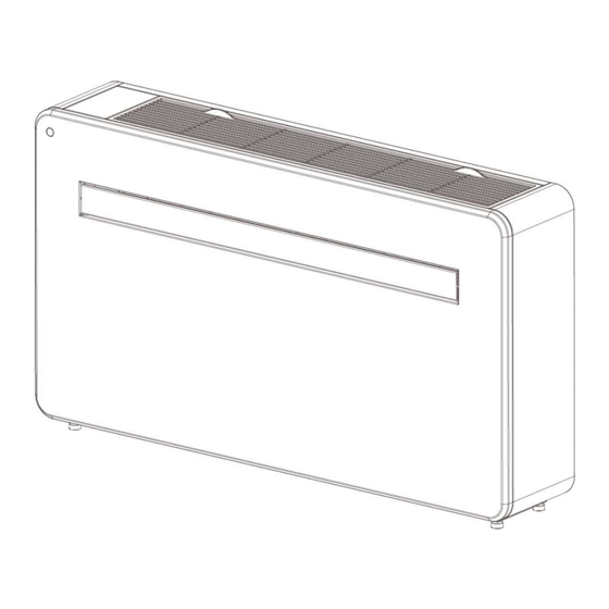
Page 4: Product Overview
PRODUCT OVERVIEW PRODUCT DIAGRAM FRONT AIR INLET CONTROL PANEL LOUVER FRONT PANEL BACK WALL HANGING MOUNTS BACK PANEL AIR INLET AIR OUTLET DRAINAGE PIPE... -
Page 5: What's Included
After the filter opened, it's PTC heater and evaporator assembly, please don't touch the PTC heater and evaporator assembly in case been cut or scalded. FEATURES Simple operation. Self-evaporative function with energy saving technology. Sleek design that seamlessly fits into any style home. ... - Page 6 VENT COVER ASSEMBLY (X2) (CHAIN, INDOOR RING AND WALL BRACKET OUTDOOR COVER) REMOTE CONTROL 2PCS TAPPING SCRE 7PCS WALL PLUGS FIXED PLATE 7PCS SCREWS (5×60mm) (4x10mm) (8×40mm) DIAGRAMS FOR ILLUSTRATIVE PURPOSES ONLY INSTALLATION TOOLS REQUIRED SPIRIT LEVEL TAPE MEASURE PENCIL SHARP KNIFE 180mm CORE DRILL...
-
Page 7: Installation
OBSTRUCTIONS FIXED ON THE WALL, WHICH WOULD PRESENT A DANGER AND/OR PREVENT COMPLETION OF INSTALLATION. INSTALLATION This unit must be installed on an external wall, as it vents directly out of its rear.and ensure the wall is flat, solid and reliable. - Page 8 Note: The machine performs best when it is installed on a wall with a thickness not exceeding 240mm. Roll the plastic vent sheets into a tube and feed them from the inside into the holes previously made. Ensure the tubes sit flush to the interior wall.
- Page 9 Once the chains are fitted and secure, any excess chain should be removed by cutting the chain. Paste the sealing strip in the accessories along the edge of the back for whole circle of the machine, cut off the excessive length if needed. Note: 1.The sealing strip should be pasted along the edge of the machine, as shown in Figure1.
- Page 10 Lift the unit onto the wall, align the hanging holes with the hooks on the hanging rail and gently rest the unit into place. At the same time, slide the drain pipe through the drainage hole. NOTE: : please ensure that the backside of product is tightly attached on the wall to avoid additional vibration and noise.
-
Page 11: Operation
OPERATION CONTROL PANEL REMOTE CONTROL The air conditioner can be controlled with the remote control. Two AAA-batteries are required. NOTE: Further details of the functions can be found on the following page. POWER Press the POWER button to turn the machine on or off. Press the MODE button to switch between cooling, heating, MODE fan and dry modes. - Page 12 FUNCTIONS Press “POWER” to turn the unit On or Off. POWER Press to change between the 4 different modes. The display will show the symbol for the mode currently selected. The cooling function allows the air conditioner to cool the room and at the same time reduces air humidity.
- Page 13 The unit has an additional PTC electric heating element. When the weather conditions outside are bad, you can press the PTC button on the remote control to turn on the electric heating function to increase PTC electric the heat. The heat power of the PTC is equal to 1000W. heating function turn on...
- Page 14 WIFI SETUP AND SMART FEATURES WIFI SETUP BEFORE YOU START Ensure your router provides a standard 2.4ghz connection. If your router is dual band ensure that both networks have different network names (SSID). The provider of your router / Internet service provider will be able to provide advice specific to your router.
- Page 15 Picture 1 Picture 2 Picture 3 WiFi CONNECTION MODE In Standby mode press and hold the speed button for 3 seconds (until you hear a bleep) to enter the WiFi connection mode. Please ensure your device is in the correct WiFi connection mode for the connection type you are attempting, the flashing of the WiFi light on your air conditioner will indicate this.
- Page 16 Picture 4 Picture 5 Picture 6 4. Enter the device connection interface after the progress bar is finished and the device is successfully as shown in the picture 7,8,9. connected, Picture 7 Picture 8 Picture 9...
- Page 17 If you don’t want to use Bluetooth connection, just need to Exit the Bluetooth connection prompt or turn off Bluetooth and follow the below steps to connect the unit with Wifi connection. 1. Click "Add Device" for operation, as shown in the picture 10. Select the type of device as “Large Home Appliance”, as shown in the picture 11.
-
Page 18: Troubleshooting
Picture 10 Picture 11 Picture 12 4. Ensure the WIFI light on the air conditioner is flashing twice per second, as shown in the picture 13. Enter the device connection interface after the progress bar is finished and the device is successfully connected. - Page 19 Doors or windows are open; there are a Close doors and windows; increase air lot of people; or in cooling mode, there conditioning power The cooling or heating are other sources of heat (e.g. fridges) effect is poor The filters screen is dirty. Clean or replace the filter screen.
- Page 20 Service and Operation for the Flammable Refrigerants R290 Please read this user’s manual carefully to ensure proper use, maintenance and installation.
- Page 21 BEFORE INITIATION To avoid damage , place the unit in an upright position for at least 24 hours before initiation. Make sure that the air outlet and air inlet are never blocked. Only operate the unit on a horizontal surface to ensure no water leaks out. WARNINGS ...
-
Page 22: Work Procedure
means that if 1 kg of this refrigerant fluid would be leaked to the atmosphere, the impact on global warming would be 3 times higher than 1 kg of CO2 , over a period of 100 years. Never try to interfere with the refrigerant circuit yourself or disassemble the product yourself and always ask a professional. -
Page 23: Repairs To Sealed Components
extinguisher adjacent to the charging area. 6. No ignition sources No person carrying out work in relation to a refrigerating system which involves exposing any pipe work shall use any sources of ignition in such a manner that it may lead to the risk of fire or explosion. All possible ignition sources, including cigarette smoking, should be kept sufficiently far away from the site of installation, repairing, removing and disposal, during which refrigerant can possibly be released to the surrounding space. -
Page 24: Repair To Intrinsically Safe Components
During repairs to sealed components, all electrical supplies shall be disconnected from the equipment being worked upon prior to any removal of sealed covers, etc. If it is absolutely necessary to have an electrical supply to equipment during servicing, then a permanently operating form of leak detection shall be located at the most critical point to warn of a potentially hazardous situation. -
Page 25: Removal And Evacuation
15. Removal and evacuation When breaking into the refrigerant circuit to make repairs – or for any other purpose – conventional procedures shall be used. However, for flammable refrigerants it is important that best practice is followed since flammability is a consideration. The following procedure shall be adhered to: •... - Page 26 • mechanical handling equipment is available, if required, for handling refrigerant cylinders; • all personal protective equipment is available and being used correctly; • the recovery process is supervised at all times by a competent person; • recovery equipment and cylinders conform to the appropriate standards. d) Pump down refrigerant system, if possible.
- Page 27 If compressors or compressor oils are to be removed, ensure that they have been evacuated to an acceptable level to make certain that flammable refrigerant does not remain within the lubricant. The evacuation process shall be carried out prior to returning the compressor to the suppliers. Only electric heating to the compressor body shall be employed to accelerate this process.
Need help?
Do you have a question about the TC12E-Monobloc and is the answer not in the manual?
Questions and answers