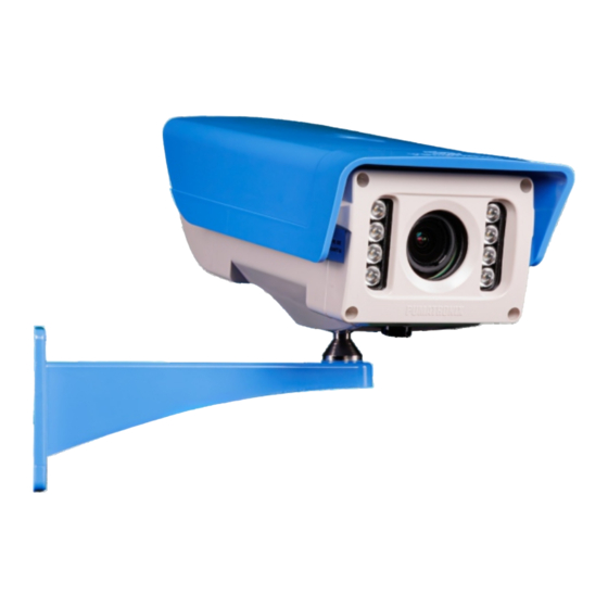
Summary of Contents for PUMATRONIX ITSCAM 450+
- Page 1 I N S TA L L AT I O N G U I D E / R E V I S I O N 1 . 0 / 2 0 24 I D E A L F O R S H O T S R E Q U I R I N G I N T E G R AT E D L I G H T I N G...
- Page 2 * Use the Ethernet cable to connect the ITSCAM 450+ to the local network and optionally to power the device. 3. Make the signal connections on ways numbered 3, 4, 9, and 10 of the 12- * Use the 12-way multi-way cable inputs to connect the ITSCAM 450+ to way multi-way cable, which can be used to receive signals from a loop, or the power source and to signal input equipment for physical triggering, such optical barrier, or on ways numbered 11 and 12 for activating illuminators.
- Page 3 7. Use the Ethernet cable for PoE power, with an RJ-45 connector, following maintenance IP must be applied. consult Pumatronix Technical Support. the ANSI/TIA-568A standard pinout: 12. Click Apply to validate the changes and wait for the device to automatically restart.
- Page 4 22. Secure the ITSCAM 450+ to the bracket by tightening the screws. 34. Adjust Zoom and Focus until the characters become clear in the image Suggestion: use a wrench longer than 10cm and in “T” shape. viewed through the Preview window, accessing the Lens tab. Line parallel to the ground 35.
- Page 5 Warranty will only be carried out in the Authorized Technical whether sensitive or not, for its operation. Assistance of Pumatronix or a third party expressly indicated by it, Pumatronix is not responsible for the purposes, use and treatment of where the product must be delivered for repair.


Need help?
Do you have a question about the ITSCAM 450+ and is the answer not in the manual?
Questions and answers