Advertisement
Quick Links
Advertisement

Related Manuals for Homaxi JB05

Summary of Contents for Homaxi JB05
- Page 1 JB05 & WM05 & TV2/TF4/TF2 INSTALLATION GUIDE V2.0.0...
-
Page 2: Installation
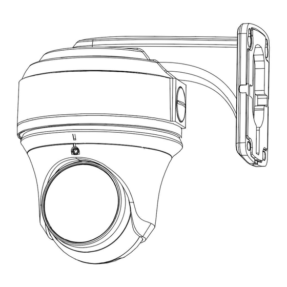
APPEARANCE AC-JB05 AC-WM05 INSTALLATION 1. Stick the mounting template to the wall where the bracket will be installed. Then drill the holes as marked on the template. 2. Insert the expansion bolts into the drilled holes and tap them in with a hammer. - Page 3 4. Fix the bracket on the wall box. 5. Loose the screws that come with the junction box, as shown below.
- Page 4 6. Match WM05 & JB05 with the four mounting screw holes, as shown below. WM05 JB05 7. Thread the tail wire through the junction box, and then align the junction box with the bracket screw holes. [NOTE] Please waterproof the threading hole between the wall mounting bracket and the junction box.
- Page 5 8. Tighten the 4 screws with black rubber ring pads to fix the junction box to the bracket. 9. Tighten the 3 screws to fix the cover to the junction box. 10. Connect the camera's tail cable. Please refer to the steps bellow to complete the RJ45 cable waterproof.
- Page 6 4) Tighten until the sealing ring is push out. 5) Optional: Use the waterproof tape to cover the RJ45 waterproof cover. 6) Finish the installation. 11. Put the cable back into the junction box through the round hole. (The round hole has enough space for...
- Page 7 [NOTE] Please do not insert the tail cable completely into the cable compartment, in order to facilitate the adjustment of the camera angle. 13. Match JB05 & TF2/TV2/TV4 with the three mounting screw holes, as shown below. TF2 Shell Camera...
- Page 8 TF4 (none AD) Shell Camera JB05 TF4 (none AD) TV2/TF4 (AD) Shell Camera TV2/TF4 (AD) TV2/TF4(AD) base JB05 [NOTE] TF4 (AD) refer to TF4 shell with active deterrence camera. Please loosen the screws, separate the camera base, and then connect the number 1 holes of the junction box.
- Page 9 TF2 Shell Camera TF4 (none AD) Shell Camera...
- Page 10 TV2/TF4 (AD) Shell Camera 15. Align the TV2/TF4 (AD ) shell camera’s slot and then attach the camera to the camera base as shown below. [NOTE] Please skip this step if your camera is TF2 model or TF4 (none AD) camera.
- Page 11 16. Power on the camera to check whether the image on the monitor is gotten from the optimum angle. If not, adjust the camera according to the figure below to get an optimum angle, and then tighten the screws or lock TF2’s cover.
- Page 12 APPENDICE JB05 Screw Hole No. on JB05 JB05 Match Camera Shell Screw Hole 1 TF4、TV2、DV2 Screw Hole 2 Screw Hole 3 Screw Hole 4 BF6、MSB62、TF1 Screw Hole 5 BF4、BV2...
- Page 13 WM05 Screw Hole No. on WM05 WM05 Match Camera & Junction Box Screw Hole 1 TF4、TV2、DV2 Screw Hole 2 Screw Hole 4 Junction Box: JB05 [NOTE] Please select the correct screw holes according to the camera shell.
Need help?
Do you have a question about the JB05 and is the answer not in the manual?
Questions and answers