Table of Contents
Advertisement
Quick Links
ZETKAMA Sp. z o.o.
ul. 3 Maja 12
PL 57-410 Ścinawka Średnia
SPRING-LOADED
SAFETY VALVES
zARMAK
TABLE OF CONTENT
1.
Principle of operation
2.
Delivery condition
3.
4.
5.
6.
7.
8.
9.
11. Installing or replacing the valve bellows assembly in the figure 600 valves
240
270
600
1. Principle of operation
The purpose of the safety valve is to protect the equipment and installation against
excessive pressure, above the pressure limit.
When the force coming from the pressure acting on the disc surmount with the force from the spring, the valve starts
to open. A further increase in the pressure, required for the particular design of the valve, causes its full opening aided
by the bell (Figure 3, item 4).
2. Delivery condition
Supplied valves are tested and set for the required opening pressure or when ordered for range - for the upper pressure
of the range (does not apply to figure 600 valves marked with ASME UV). Valves are stamped on a nameplate fixed
to the body and with the signs on the edge of the outlet flange.
USER MANUAL
240, 270, 600, 610, 613, 614
630, 650, 670, 673, 674, 775
610
613
614
1 / 16
630
650
670
Edition: 6/2024
Date: 06.10.2024
673
674
775
Advertisement
Table of Contents

Related Manuals for Zetkama zARMAK 240


Summary of Contents for Zetkama zARMAK 240
-
Page 1: Table Of Contents
ZETKAMA Sp. z o.o. ul. 3 Maja 12 PL 57-410 Ścinawka Średnia USER MANUAL SPRING-LOADED 240, 270, 600, 610, 613, 614 Edition: 6/2024 SAFETY VALVES 630, 650, 670, 673, 674, 775 Date: 06.10.2024 zARMAK TABLE OF CONTENT Principle of operation... - Page 2 Nameplate For valve 240, 270, 610, 613, 614, 630, 650, 670, 673, 674, 775 Symbols: 1 Type of safety valve 2. Bore diameter 3. Spring number 4. The discharge coefficient for vapours and gases 5. Set pressure or set pressure range 6.
-
Page 3: Installation Of Safety Valves
3. Installation of safety valves • Before the installation on the unit or pipeline, check if valve was not damaged or contaminated during transport. It is necessary to check the cleanliness of flow channels, external surfaces and end connections. Surfaces of flanges should be cleaned of preservative and of any possible impurities. -
Page 4: Operation Of Safety Valves
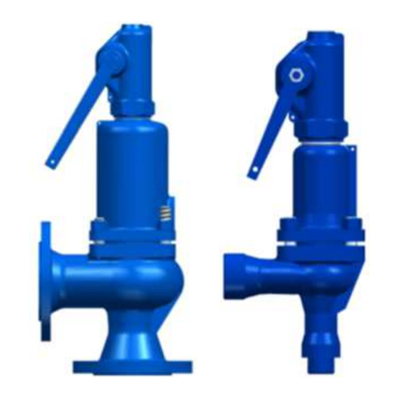
Operation of safety valves 630AC, 630CE 630FF, 630FG 775BC 240AC, 240FE, 240RE 630FE, 630RE 1 Body Seat / Inlet nozzle Disc Bell 5 Bonnet Stem Spring Body Inlet nozzle Disc Bell Bonnet Stem Spring Adjusting ring Body nut Body screw Insert Locking pin Locking screw... - Page 5 Clodes Open Drawing 4 Checking the safety valve operation involves lifting of the disc with a lever, running it in the direction indicated in Drawing 4. Starting the lever causes loosening of the spring force thereby allowing the minimum lift of the disc and the flow of medium.
-
Page 6: Adjustment Of The Set Pressure
Drawing 6 Drawing 5 Drawing 7 5. Adjustment of the set pressure The pressure may be adjusted by an authorized person, i.e. Authorized Technician and Inspector of a Notified Body (UDT, TUV). To change the response pressure or replace the springs, the seal must be removed, which causes the warranty to expire. -
Page 7: Replacing The Spring
Unscrew the cap assembly (19) Loosen the lock nut (17) Turn the adjusting screw (18) to achieve the required pressure for the opening. in order to protect the surface of the sealing, while turning an adjusting screw hold the stem (6) with the lifting nut (21) preventing it from rotation Lock the lock nut (17) Turn the cap assembly (19) don’t forget about new gasket (16) -
Page 8: Replacing The Gasket Between The Bonnet And The Cap
8. Replacing the gasket between the bonnet and the cap To replace the gasket, the seal (22) between the bonnet and the cap, which will void the warranty. In the case of valves covered by warranty, these activities must be performed by the manufacturer or a person designated by it or an institution with appropriate authorizations. -
Page 9: Replacing The Inlet Nozzle In The Figure 600 Valves
first screw in the nuts (14) on the longer bolts evenly and alternately, and then screw in the nuts on the shorter bolts. 15. Turn the adjusting screw (18) to achieve the required opening pressure. In order to protect the contact surfaces, while turning, hold the stem (6) by the nut (21) to prevent it from turning 16. -
Page 10: Maintenance And Repairs Of Safety Valves
Drawing 8 16. Screw the new nozzle (2) into the body (1), remembering to replace the gasket between the body and the nozzle and between the locking screw (29) and the body with new ones. 17. Screw the adjusting ring (27) onto the nozzle (2) and adjust it to the height determined in accordance with point 13 18. -
Page 11: Operating Disturbances And Their Elimination
• sealing surfaces of the seat and disc should ensure tight closure of the valve; • All cooperating moving parts of valve mechanism should maintain movability in operating conditions. In order to maintain these conditions the valves should be periodically inspected and renovated. Inspections of safety valves should be conducted by persons with adequate authorisation. - Page 12 If the properties of the medium and the operating conditions do not exclude such possibility - appropriate frequency of "Seizing" of the sealing surfaces of the inspections and repairs of the safety valve seat and valve disc preventing their must be adapted, and the time of valve separation at the set pressure check provided in the operating records of protected device / system should be...
- Page 13 deformed due to excessive load are permanent- replace the safety valve transferred from the pipes, causing, with a new one. among others, leaking. Depending on the reason diagnosed - according to the indications and decision Other causes of leaks on the seat. of the manufacturer - replace the defective parts or replace the safety valve with a new one.
- Page 14 installation. Consider the possibility to use safety valves with support lugs. Reduce flow resistance in the supply line. Too high flow resistance in the supply If this is not possible, for some reasons - line - pressure loss in the supply line consider the possibility of a safety valve exceeds 3% (set pressure of safety with damper.
- Page 15 Crew injuries at discharge instructions (e.g. near the platforms for condition and external medium service staff) leakage Use of safety valve without external Use valve with gastight construction, that tightness test confirmed by the is with external tightness test of the valve. manufacturer Replace sealing in the operating valve with Use of valve in which sealing is not...
-
Page 16: Valve Service Discontinuity
- The guarantee does not cover an assembly of third party spare parts and design changes made by the user, as well as changes in set pressure and natural wear and tear. - The user should inform ZETKAMA about latent defects of the product immediately after they are found. - The complaint must be made in writing.
Need help?
Do you have a question about the zARMAK 240 and is the answer not in the manual?
Questions and answers