Table of Contents
Advertisement
Quick Links
Advertisement
Table of Contents

Related Manuals for MUNIC C4D-4MEUAF V8


Summary of Contents for MUNIC C4D-4MEUAF V8
- Page 1 C4D-4MEUAF_V8 - INSTALLATION GUIDE V 1.2 27/07/2022...
-
Page 2: Table Of Contents
Table of contents Preface............................. 3 Warnings and notices ......................3 RF Exposure Information (SAR) ................. 3 1. Hardware features ......................4 2. Hardware description ...................... 5 2.1 External view ........................ 5 2.2 Internal view ......................... 5 2.3 OBD connector pin out .................... 6 2.4 OBD adapter wires ..................... -
Page 3: Preface
MUNIC Car Data can in no event be held liable for technical or editorial errors or omissions herein, nor for incidental, special or consequential damages from the furnishing, performance, or use of this installation guide. -
Page 4: Hardware Features
1. Hardware features OBD Dongle Performance Processor ARM A7 2 Gbytes NAND Flash 2 Gbytes Power supply External power supply 8-18V ⎓ 2A max* range External voltage ● measurement Li-pol battery 450mAh Communication Modem LTE Cat M1 & EGPRS Module (BG96) Bands LTE: band 3, 8, 20, 28 GSM-900 and GSM-1800... -
Page 5: Hardware Description
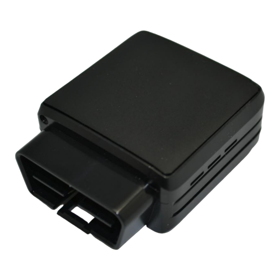
2. Hardware description 2.1. External view 1 : OBD connector 2 : micro USB connector 3 : bicolor led 2.2. Internal view 5 : GNSS antenna 6 : micro SIM holder 7 : Internal battery* * Please read warnings section at the beginning of the installation guide... -
Page 6: Obd Connector Pin Out
2.3 OBD connector pin out Pin # Comment OEM specific J1850+ (PWM/VPW) OEM specific Chassis ground Signal ground CAN High K line OEM specific J1850- (PWM) OEM specific CAN low L line Battery voltage 2.4 OBD adapter wires This adapter is only used to connect the OBD to a computer (laptop/desktop). Pin # Wire color Yellow... -
Page 7: Preparing/Installing The Device
3. Preparing/installing the device Those operations may need the use of specific tools like : Small cross-head screwdriver for the screw. Small slotted screwdriver to remove the cover. Thin tweezers to insert/remove the SIM card. 3.1. Open the device Remove the screw using Small cross-head screwdriver Insert slotted screwdriver to pop-out the top cover and extract it. - Page 8 Device is now open...
-
Page 9: Insert The Sim Card
3.2. Insert the SIM card The micro SIM card slot is located between the two electronic cards. Insert the card with contact on bottom into the slot and push it as far as it will go. Once inserted the SIM card looks like this:... -
Page 10: Properly Close The Device
3.3. Properly close the device First, check that the hole of the electronic card is correctly inserted in the plastic part. If it’s not inserted please move smoothly the electronic cards right and left to place it in correct position. GOOD NOT GOOD Second, insert the GPS antenna as shown below. - Page 11 Second, check that the micro USB port is correctly inserted on its place. If it’s not inserted please move smoothly the electronic cards to place it in correct position. NOT GOOD GOOD...
-
Page 12: Install The Obd Dongle
insert the GPS antenna as shown below. Finally, insert the battery and place the screw. 3.4. Install the OBD Dongle Connect the OBD Dongle on your vehicle OBD connector. -
Page 13: Led Sequences
2000ms OFF Shutdown/Hibern 30ms ON / 1 s OFF Idle/Sleep 30ms ON / 1 s OFF 5. EU Regulatory We, MUNIC declares that the radio equipment type C4D-4MEUAF_V8, is in compliance with the Directive 2014/53/EU. Technology/Band Mode Conduct Power (dBm) GLONASS...
Need help?
Do you have a question about the C4D-4MEUAF V8 and is the answer not in the manual?
Questions and answers