Table of Contents
Advertisement
Quick Links
Advertisement
Table of Contents

Related Manuals for MUNIC C4D-4G4USAA V8+


Summary of Contents for MUNIC C4D-4G4USAA V8+
- Page 1 C4D-4G4USAA_V8+ - INSTALLATION GUIDE V 1.6 21/12/2021...
-
Page 2: Table Of Contents
Table of contents Preface ..........................2 Warnings and notices .......................2 FCC Regulations ....................... 3 FCC RF Exposure Information (SAR) ..............3 1. Hardware features ......................5 2. Hardware description ....................6 2.1 External view ......................6 2.2 Internal view ......................6 2.3 OBD connector pin out ..................7 2.4 OBD adapter wires ....................7 3. -
Page 3: Preface
MUNIC Car Data can in no event be held liable for technical or editorial errors or omissions herein, nor for incidental, special or consequential damages from the furnishing, performance or use of this installation guide. -
Page 4: Fcc Regulations
FCC Regulations This device complies with part 15 of the FCC Rules. Operation is subject to the following two conditions: (1) This device may not cause harmful interference, and (2) this device must accept any interference received, including interference that may cause undesired operation. - Page 5 For this device, the highest reported SAR value for usage near the body is 1.34 W/kg. For this device, the highest reported SAR value for usage on extremity is 3.30 W/kg. While there may be differences between the SAR levels of various devices and at various positions, they all meet the government requirement.
-
Page 6: Hardware Features
1. Hardware features OBD Dongle Performance Processor ARM Cortex-A7 Dual-Core 1.2GHz 256 Mbytes NAND Flash 512 Mbytes Power supply External power supply 8-18V range ● External voltage measurement Internal battery Li-pol battery 270mAh Communication Modem 4G Cat.4 module EC25-T Bands B2, B4, B5, B12, B66, B71 Modem antenna Internal... -
Page 7: Hardware Description
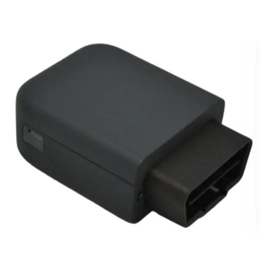
2. Hardware description 2.1. External view 1 : OBD connector 2 : micro USB connector 3 : signal bicolor led 4 : power bicolor led 2.2. Internal view 2 : micro USB connector 5 : Modem antenna 6 : GNSS antenna 7 : nano SIM holder* 8 : Internal battery** * SIM holder can be absent if device have eSIM chip. -
Page 8: Obd Connector Pin Out
2.3 OBD connector pin out Pin # Comment OEM specific J1850+ (PWM/VPW) OEM specific Chassis ground Signal ground CAN High K line OEM specific J1850- (PWM) OEM specific CAN low L line Battery voltage 2.4 OBD adapter wires This adapter is only used to connect the OBD to a computer (laptop/desktop). Pin # Wire color Yellow... -
Page 9: Preparing/Installing The Device
3. Preparing/installing the device Those operations may need the use of specific tools like : T4 Torx screwdriver for the external screw. T6 Torx screwdriver for the internal screw. Small slotted screwdriver to remove the cover. Thin tweezers to insert/remove the SIM card. 3.1. - Page 10 Remove the screw located on each side of the OBD connector using T4 Torx screwdriver Remove the screw located on the PCB at the bottom of the device using T6 Torx screwdriver Move apart the side of the device first and then pull the OBD connector out of the body.
- Page 11 Device is now open...
-
Page 12: Properly Close The Device
3.2. Properly close the device First, insert the main part into the bottom cover. Insert the rear first and take care of the pogo pin of the GNSS antenna. Once inserted, push the main part into the back cover until your hear two “clac” Place the long screw on the rear of the electronic cards in order to fix it to the body using T6 Torx screwdriver. - Page 13 Place the screw on each side of the OBD connector to fix it to the body using T4 Torx screwdriver. Insert the top cover beginning with the rear. Finally, push the top cover down until you hear the “clac”. Device is ready.
-
Page 14: Install The Obd Dongle
Modem OK 2000ms ON /Fix GNSS 2000ms OFF Shutdown/Hibern 30ms Green ON / 1s 30ms Green ON / 1s Idle/Sleep 5. Support For all questions not related in this installation guide, please contact the support team by support@munic.io email at...
Need help?
Do you have a question about the C4D-4G4USAA V8+ and is the answer not in the manual?
Questions and answers