
Related Manuals for PMI DORO

Summary of Contents for PMI DORO
- Page 1 DORO Headrest System Aluminum ® Instruction Manual Document no.: 3000-90_EN Version: Date of creation: 1998-09-19 Last revision: 2017-08-29...
-
Page 2: Quick Guide
Quick Guide Quick Guide DORO QR3 Skull Clamp, ® item-no. 1001.001 Receptacles for Skull Pins Generation Quick-Rail®) Torque Screw Index Knob Rocker Arm Starburst Starbursts Quick-Rail® Generation Skull Clamp Extension Assembly Skull Clamp Base Quick-Release Knob $aei4 $aed4 $aeu4 $aet4... - Page 3 Quick Guide DORO Swivel Adaptor Aluminum, ® item-no. 3002-00 Upper Starburst Connection Upper Locking Screw Swivel Base Lower Locking Screw Lower Starburst Connection $aei4 $aet4 $aed4 $aeu4 $aei3 $aet3 $aed3 $aeu3 $aei2 $aet2 $aed2 $aeu2 $aei1 $aet1 $aed1 $aeu1 Rev. Änderung / Revision text...
-
Page 4: Table Of Contents
Components description 12 Additional components 13 Technical specifications 15 Outline drawings 16 Mounting 18 Mounting of the DORO Adjustable Base Unit 18 ® Mounting the DORO Base Unit to a standard OR Table 20 ® Mounting the DORO Swivel Adaptor ... - Page 5 Secure the patient‘s head to the Skull Clamp 24 Connecting the Skull Clamp to the Swivel Adaptor 28 Function and safety inspection 29 Prior to clinical use of a DORO device 29 ® After clinical use of a DORO device ...
-
Page 6: Regulatory Information
Declaration of manufacturer under sole responsibility, that the medical de- vice meets all the provisions of the directive 93/42/EEC which apply to it. FDA registration The DORO Headrest and Retractor Systems are registered with the ® 510(k) Numbers K001808, K032331, K063494. -
Page 7: General Safety Information
General Information General Safety Information Symbols used for safety information This instruction manual contains the basic information required for the safe use of the device. The symbols explained below might be used in this instruction manual and/or on the product labels to point out safety-relevant information: Danger: This symbol indicates a danger to the health of the patient. - Page 8 General Information Manufacturer: Manufacturer's name and address. Date of manufacture: Printed on package! Safe usage until: Printed on package! Do not use after this date. Sterile: Sterilized with gamma radiation or ethylene oxide according to the label on the outside box. Use only once: Do not reuse! Destroy after usage! MR safe:...
-
Page 9: Proper Handling And Permitted User
General Information Proper handling and permitted user The device may only be used and applied by qualified professionals belonging to the operating team. Creutzfeldt Jakob Disease Warning: If the patient is suspected of having the Creutzfeldt Jakob Disease, adequate measures must be taken to prevent possible transmission to other patients, users, and third parties. -
Page 10: Basic Information
General Information Basic information Warranty and liability All warranty claims presuppose proper operation and treatment of the device. The manufacturer guarantees that all parts are free from defects in both materials and workmanship at the time of delivery. Exclusion of liability: The manufacturer shall not be liable for damages resulting from incor- rect use of the device, failure to follow the instructions furnished in this manual or improper or insufficient maintenance. -
Page 11: Use As Per Instructions
General Information Use as per instructions The device is designed and built according to the latest technical deve- lopments and to approved safety standards. DORO Headrest and Retractor Systems may be used ® • only as a support mechanism for head and neck surgery, •... -
Page 12: Product Description
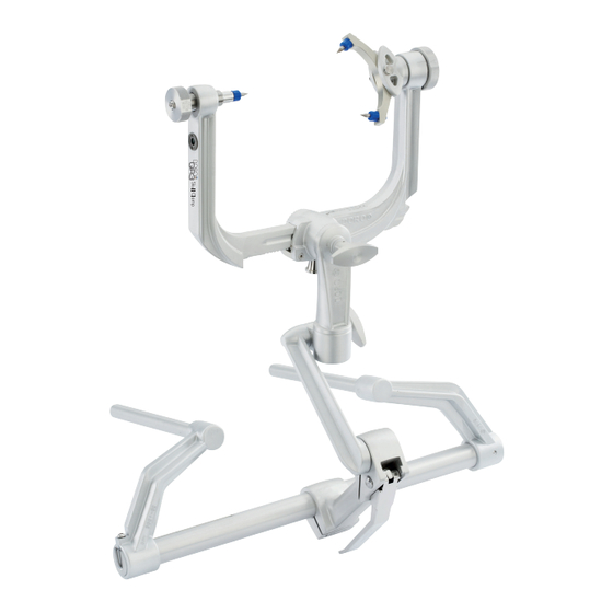
Product description Intended use The DORO Headrest System is a mechanical support system which is used in head and neck surgery. This system allows the patient’s head to be positioned and secured for the operation. It can be used for cranial fixation of the patient in prone, supine, lateral and sitting positions. -
Page 13: Additional Components
Product List and Components Note: For patients undergoing surgery in sitting positions, use the DORO ® Crossbar Adaptor (item no. 3007-00) which is mounted to the side rails of the OR Table (see instruction manual DORO Crossbar Adaptor for ®... - Page 14 ® DORO Swivel Adaptor Navigation ........3002-60 ® 5.5.4 Additional DORO Navigation Adaptors ® (refer to instruction manual Navigation Adaptors): Used with DORO Skull Clamp 3003-00: ® Description: Item-no.: DORO Navigation Adaptor Quick-Rail®, Stryker®, Alu ..3114-64 ® DORO Navigation Adaptor Quick-Rail®, Medtronic, Alu ..3114-65 ®...
-
Page 15: Technical Specifications
Cervical Spine Support ..........3012-00 ® DORO Headrest Wall Storage Unit ........3013-00 ® For more accessories and product pictures please refer to our DORO ® Cranial Stabilization and Retractor Systems brochure or visit us at www.pmisurgical.com. Exclusion of liability:... -
Page 16: Outline Drawings
Product List and Components Outline drawings 300-430 85-215 24,5 24,0 DORO QR3 Skull Clamp, item no. 1001.001, in mm. ® DORO Skull Clamp, item no. 3003-00, in mm. ® Instruction Manual -16- pro med instruments... - Page 17 Product List and Components DORO Quick-Clamp, item no. 1202.014, in mm. ® DORO Quick-Clamp ® /w Interface for Mizuho-Type Retractors, DORO Swivel Aaptor, item no. 3002-00, in mm. ® item no. 1201.045, in mm. DORO Adjustable Base Unit, item no. 3001-00, in mm.
-
Page 18: Mounting
Base Unit is connected to the OR Table. 6.1.1 Adjusting the DORO Base Unit to a standard OR Table 1. Remove the Hex Wrench from its storage holder on the lefthand side of the Connecting Tube. - Page 19 Mounting 6. Make sure that the Hex Screw is seated properly in the slot of the connecting tube. Using the Hex Wrench, lock the width by turning the Hex Screw clockwise. Return the Hex Wrench to its storage holder. Once this adjustment is made for your OR Table, this step can be skipped in future use.
-
Page 20: Mounting The Doro
Mounting Mounting the DORO Base Unit to a standard OR Table ® 1. Position the Base Unit at the head of the OR Table with the Base Handle Assembly centered on the connecting tube. 2. If you need to adjust the Base Unit to the width of the receptacles of the OR Table see chapter 6.1.1. -
Page 21: Mounting Of The Doro
The teeth of the starburst connections must be fully engaged and seated properly. Danger: Check all fastening screws and all starburst locking mechanisms on the device and check the stability of the complete DORO system before ® and after each clinical use. Make sure that the device is exactly mounted as described in this manual. -
Page 22: Mounting Additional Accessories
Mounting Additional Accessories 6.7.1 Quick-Clamp w/ Interface for Mizuho-Type Retractors Use the Quick-Clamp w/ Interface for Mizuho-Type Retractors, item no. 1201.045, to connect Mizuho-Type Retractors to the DORO Skull ® Clamp 3003-00 or 1001.001. 1. Mount the Quick-Clamp w/ Interface for Mizuho-Type Retractors (item no. - Page 23 Interface for Mizuho-Type Retractors by turning it clockwise. The teeth of the starbust connections must be fully engaged and seated properly. 6.7.2 Quick-Clamp and Accessories Connecting the DORO Quick-Clamp to the Skull Clamp 3003-00 or ® 1001.001. Mount the DORO Quick-Clamp (item no.
-
Page 24: Use And Handling
Use and Handling Note: The user decides the best approach to secure the patient to the Skull Clamp. We recommend to secure the patient‘s head first to the Skull Clamp with Skull Pins and then to connect the Skull Clamp carefully by means of the Swivel Adaptor to the Base Unit and the OR Table. - Page 25 performed by a licensed physician or a licen- INCORRECT sed surgeon. Danger: A patient fixated with this DORO Headrest ® System and positioned on the table top of a surgical table system must not be transferred to or from the OR table column. This might cause severe injuries in case of collision.
- Page 26 The user decides which type of fixation and what clamping force are required, based on the thickness of the skull and the bone structure. Therefore: refer to the instruction manual Skull Pins. For pediactric cases we recommend the DORO Multi-Purpose Skull Clamp with 4-point ®...
- Page 27 When applying pressure the first line (20lbs/90N) becomes visible, then the second line and the third line become visible. Danger: The DORO Skull Clamp may cause damage to the patient’s skull. ® The head may fall out of the Skull Clamp or the Skull Pins may break through into the brain if using an incorrect clamping force.
-
Page 28: Connecting The Skull Clamp To The Swivel Adaptor
Connecting the Skull Clamp to the Swivel Adaptor 1. After securing the patient‘s head to the Skull Clamp, position the patient’s head exactly as required for surgery and stabilize the head. Carefully hold the patient‘s head and Skull Clamp while proceeding. 2. -
Page 29: Function And Safety Inspection
Danger: Check all fastening screws and the stability of the Headrest and Retractor System before and after each clinical use. Prior to clinical use of a DORO device ® Perform the following function and safety tests before using the device... -
Page 30: After Clinical Use Of A Doro ® Device
Function Safety After clinical use of a DORO device ® Perform the following function and safety tests after having used the device in clinical applications: Make sure: • that the device is complete and is not damaged. If the device ap-... -
Page 31: Care
Care and Cleaning Care Before initial use, make sure to reprocess the product according to the instructions given in the following pages. Manual Cleaning Clean, inspect and test the device carefully. A good cleaning and main- tenance procedure will extend the useful life of the device. Cleaning and rinsing must take place immediately after each use for best effect. -
Page 32: Automated Cleaning
Care and Cleaning and any hard to reach areas. If the device has sliding mechanisms or hinged joints, actuate the area to free any trapped blood and debris. Brush delicate features of the instruments with care to avoid bending or breaking of such features. Using a syringe filled with cold tap water, flush internal areas that cannot be accessed with a brush for at least 20 seconds with a static water pressure of at least 4.2 bar. - Page 33 Care and Cleaning Dry immediately after final rinse. Use the drying cycle of the washer/ disinfector and – if required – a clean lint-free cloth for drying. Dry internal areas with filtered compressed air, if available. Inspect each component for remaining debris; if any are present, repeat the cleaning procedure using fresh detergent.
-
Page 34: Lubrication
Care and Cleaning Lubrication Lubrication according to the subsequent lubrication drawing should be done after every wash. Failure to lubricate the Headrest System and Re- tractor System as recommended will result in a greatly reduced lifetime of the equipment. You can lubricate with any medical grade lubricant. Warning: Failure to proper lubricate as instructed will increase friction between the moving parts of the device, which may damage them. -
Page 35: Lubrication Drawing
Care and Cleaning Lubrication drawing $aei4 $aet4 $aei3 $aet3 $aei2 $aet2 $aei1 $aet1 Rev. Änderung / Revision text Kanten / Edges Toleranz / Tolerance Gewicht / Weight Maßsta $field4 $raw $weight Hinweis: $field2 Projektion / Format projection method Notice: $field3 Datum / Date pro med instruments Gm Name... - Page 36 Care and Cleaning $aei4 $aet4 $aei3 $aet3 $aei2 $aet2 $aei1 $aet1 Rev. Änderung / Revision text Kanten / Edges Toleranz / Tolerance Gewicht / Weight Maßstab / Scale Werkstoff / Material $field4 $raw $mat $weight Hinweis: $field2 Projektion / Format / Size Erstverwendung / First used projection method $field1...
-
Page 37: Maintenance And Repair
Maintenance and Repair Maintenance and repair 10.1 Maintenance intervals The purchaser shall be obliged to send the device to the manufacturer or to the authorized distributor once a year for maintenance. The ma- nufacturer will perform all required repair work. Exclusion of liability: The manufacturer shall not be liable for damages resulting from the failure of the purchaser or user to submit the device for maintenance. - Page 38 Maintenance and Repair 10.2 Maintenance to be performed by the purchaser The Base Unit is adjustable in all directions. Frequent realignment of the Base Unit may cause the adjustable parts to loosen. Therefore, we strongly recommend performing the following maintenance work on a regular basis: 10.2.1 Adjusting the Locking Lever...
- Page 39 Maintenance and Repair Note: The Locking Lever must be open, while readjusting the Tension Knob. Ensure that the Locking Lever lip is properly placed under the two Stainless Steel pegs. WARNING: The Locking Lever should not be removed and should never be forced into place.
- Page 40 Maintenance and Repair 10.2.3 Replacing the Transitional Member 1. Open the Locking Lever by lifting up to release. 2. Removing: Align the Transitional Member with the slot of the base handle assembly at an angle of 90°. Remove the Transitional Member from the Base Handle Assembly by pulling it slowly to the left- hand side (or to the right-hand side).
- Page 41 Maintenance and Repair Danger: Push until the click can be clearly detected. US-Version: Turn the ma- nual lock counter-clockwise completely until you have reached the end position. Ensure that the Transitional Member is safely locked in the Base handle assembly. Otherwise, the system stability is not ensured. Do not use Transitional Members provided by other manufacturers.
-
Page 42: Environmentally Compatible Disposal
Environment Appendix Environmentally compatible disposal The purchaser or user is responsible for rendering the device unusable if it is no longer to be applied (prevention of misuse). Disposal: Segregate the components of the device according to material (alumi- num, high performance polymer materials, etc.) for recycling. You can return old devices to the manufacturer or authorized distributor. -
Page 43: Manufacturer Information
GmbH Bötzinger Str. 38 79111 Freiburg, Germany Phone +49 761 384 222 10 +49 761 384 222 80 E-Mail pmi@pmisurgical.com Website http://www.pmisurgical.com US Subsidiary: pro med instruments, Inc. 4529 SE 16th Place, Suite # 101 Cape Coral, FL 33904... - Page 44 ® instruments GmbH (PMI). All rights reserved. Third party registered trademarks, product images, designs and trade names are the property of their associated registrants and no claim of association is made. Any and all names of third party companies, including third party company logos, product images, and product names are used for descriptive purposes only.
Need help?
Do you have a question about the DORO and is the answer not in the manual?
Questions and answers