Table of Contents
Advertisement
Quick Links
Advertisement
Chapters
Table of Contents

Related Manuals for Jupiter CRS-5K


Summary of Contents for Jupiter CRS-5K
- Page 1 CRS-5K Hardware Manual May 23, 2022 A-CAN-001-03, Rev. A...
- Page 2 Jupiter Systems owns the copyright for this manual. Use or reproduction of this manual in parts or entirety without the authorization of Jupiter Systems is prohibited. The contents of this manual are subject to change without notice to improve quality.
-
Page 3: Table Of Contents
2.2 CRS-5K Connections and Buttons........ - Page 4 5.2 Jupiter Canvas Hardware ........
-
Page 5: Chapter 1. Introduction
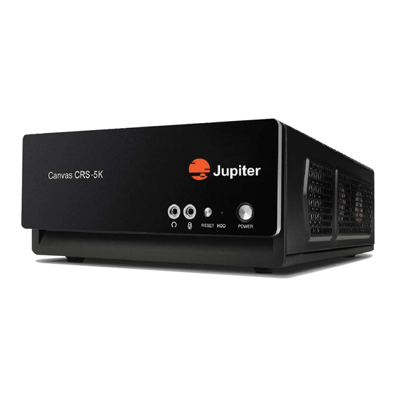
NTRODUCTION 1.1 CRS-5K Features The Canvas CRS-5K system is a small but powerful computer designed for rapid sharing of presentations in a meeting room. With the Canvas CRS-5K system, teams in huddle rooms can quickly collaborate using live video (streaming), applications, document presentations, and web windows. -
Page 6: Crs-5K Functionality
Remote PCs via VNC • Windows applications • Shared desktops • Shared Video calls 1.2.2 CRS-5K Displays The CRS-5K may be used as a Client in a larger Canvas system, sharing sources and canvas across the network. CRS-5K Hardware Manual... -
Page 7: Hardware Features & Specifications
2.1 Hardware Features & Specifications With a built-in graphics adapter, the CRS-5K delivers up to four 1K outputs or a single 4K/5K output. It has four USB 3.0 compliant ports, one Ethernet port, a microphone input, and an audio output which can be used with a headset or an amplified speaker system. - Page 8 Chapter 2: Specifications and Connections Table 2.1: CRS-5K Specifications Item Description INTERFACE PORTS 4 USB 3.0, A type 3.5mm stereo, (AC’97 and HD audio), digital audio output, microphone Audio Network 1 RJ45 OUTPUT PORTS Interface Mini-Display Port Max Output Resolution...
- Page 9 Hardware Features & Specifications Table 2.1: CRS-5K Specifications Item Description SOFTWARE Windows 10 Management Software Canvas Encryption SSL/TLS Client Software Canvas Desktop & Web Application Support TCP/RS232 Picture Viewer Scrolling Text Clock Yes, multiple time zones CONFIGURATION CAPACITY 5K display (5120 x 2160 @60Hz)
-
Page 10: Crs-5K Connections And Buttons
CRS-5K. A convenient feature of the CRS-5K is that regardless of which port cables are used, Windows will build a display wall using the monitors in the order which they are connected. There is no set physical numbering of the chassis ports. -
Page 11: Output Limits
CRS-5K Connections and Buttons 2.2.1.2 Output Limits The CRS-5K supports up to four HD displays (1920 x 1080 @60Hz) or four 4K display (up to 3840 x 2160 @60Hz) or three 5K display (up to 5120 x 2160 @60Hz). 2.2.1.3 Cables and Adapters The mini DisplayPorts are the primary outputs. -
Page 12: Front Panel Button, Connectors And Led
Chapter 2: Specifications and Connections 2.2.2 Front Panel Button, Connectors and LED Figure 2.2: CRS-5K Front Panel • 3.5 mm Audio Out • 3.5 mm Microphone In • Reset button • HDD LED (Shows activity when blinking) • Power button... -
Page 13: Chapter 3. Wall Configuration
Figure 3.1: Window Screen Resolution Pane Note: The screen may go black if the wrong resolution is chosen. The CRS-5K will revert to the last working resolution in a short while. Select the Resolution dropdown in the dialog box and choose the desired resolution With multiple displays connected, the monitors may be dragged into the geometry you desire on the Screen Resolution pane. - Page 14 Multiple display types may be connected (e.g., a Samung on port 1, a Mitsubishi on port 2, an NEC on port 3, etc.). You can connect different connector types (e.g., DisplayPort on port 1, HDMI on port 2, DVI on port 3, etc.). The officially supported configuration is up to four 1080p monitors or one 4K/5K monitor. CRS-5K Hardware Manual...
-
Page 15: Chapter 4. Removing & Replacing Components
Disconnect all appropriate cables from the Rear Panel connector(s) on the board/assembly you are replacing Caution: Unplug the AC power cord from the CRS-5K chassis. Remove the cover Remove the 12 screws which retain the top cover on the CRS-5K chassis b Remove top cover from CRS-5K chassis. CRS-5K Hardware Manual... -
Page 16: Battery Replacement
WARNING! There is danger of explosion if the battery is incorrectly replaced. Replace only with the same or equivalent type recommended by Jupiter Systems. Dispose of used batteries according to the manufacturer’s instructions. Avertissement! Il y a danger d’explosion s’il y a remplacement incorrect de la batterie. Remplacer uniquement avec une batterie du même type ou d’un type équivalent recommandé... -
Page 17: Memory Support
Populating these DIMM slots with a pair of memory modules of the same type and size will result in interleaved memory, which will improve memory performance. 4.3.2 SO-DIMM Module Population Sequence When installing memory modules, the DIMM slots must be populated in the following order: DIMMA1, then DIMMB1. CRS-5K Hardware Manual... -
Page 18: So-Dimm Installation
Position the SO-DIMM module's bottom key so it aligns with the receptive point on the slot. Take note of the module's side notches and the locking clips on the socket Figure 4.3: Orienting DIMM Module Insert the SO-DIMM module straight down CRS-5K Hardware Manual... -
Page 19: Figure 4.4 Inserting Dimm Module
Memory Support and Installation Figure 4.4: Inserting DIMM Module Press down until the module locks into place. The side clips will automatically secure the SO-DIMM module, locking it into place Figure 4.5: Lock DIMM Module CRS-5K Hardware Manual... -
Page 20: So-Dimm Removal
Chapter 4: Removing & Replacing Components 4.3.4 SO-DIMM Removal Use your thumbs to gently push the side lips near both ends away from the module. This should release it from the slot. Pull the SO-DIMM module upwards. Figure 4.6: Remove DIMM Module CRS-5K Hardware Manual... -
Page 21: Chapter 5. Warranty & Technical Support
Expense for the return shipment of the product to the customer within the U.S. will be borne by Jupiter. Products returned to Jupiter must have a Return Merchandise Authorization (RMA) number. To obtain an RMA number contact the Jupiter repair service center at the phone number listed on the Copyright page. -
Page 22: Limitations
Jupiter product. Jupiter shall not be held liable for incidental, indirect, consequential, general or special damages resulting from the use or the inability to use or the failure of a Jupiter product used in any application. No warranty, including this warranty, shall apply to any Jupiter products that have been modified in any way, by any organization other than the Jupiter factory. -
Page 23: Hardware Faults
If you require technical assistance, please contact Jupiter Systems' technical support team. Please provide as much information to the support team about the fault and any steps you have taken in trying to resolve the issue. - Page 24 This page has been intentionally left blank CRS-5K Hardware Manual...
-
Page 25: List Of Figures
List of Figures Figure 1.1 CRS-5K Front Panel ......................1 Figure 2.1 CRS-5K Rear Panel .......................6 Figure 2.2 CRS-5K Front Panel ......................8 Figure 3.1 Window Screen Resolution Pane ...................9 Figure 4.1 CRS-5K CPU Board ......................12 Figure 4.2 Memory Location ......................... 13 Figure 4.3... - Page 26 This page has been intentionally left blank CRS-5K Hardware Manual...
-
Page 27: Index
Picture Viewer DisplayPort Picture-in-Picture DisplayPorts Power button Displays Power Specifications Encryption Rated Voltage Rear Panel Connections Remove and Replace Components Battery Reset Features Resolution Form Factor RJ45 Ethernet Port Frequency Front Panel Button, Connectors and LED RTSP CRS-5K Hardware Manual... - Page 28 CRS-5K Hardware Manual Index Using Microsoft Windows Scrolling Text 1, 4 SimpleShare Software Decoding Temperature, Operating Wall Configuration Wall Geometry Weight Shipping Unit USB 3.0/2.0/1.1 ports CRS-5K Hardware Manual...
Need help?
Do you have a question about the CRS-5K and is the answer not in the manual?
Questions and answers