Table of Contents
Advertisement
Quick Links
Advertisement
Table of Contents

Related Manuals for CPAT FLEX DRV3

Summary of Contents for CPAT FLEX DRV3
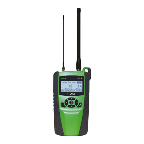
- Page 1 DRV3 Portable Digital Leakage Receiver Please direct all questions to your local CPAT Flex sales office representative, or distributor, or contact CPAT Flex technical support at: www.cpatflex.com. Copyright 2024 CPAT Flex Inc. All rights reserved.
- Page 2 CPAT Flex accepts no liability for any omissions or errors present in this document or for any damages that may arise from the utilization of the information provided herein.
-
Page 3: Table Of Contents
1.3.2 FCC Part 15 Class A 1.4 Technical Support 1.5 Calibration 1.6 CPAT Flex Website 2. System Components 2.1 Initial Verification 2.2 DRV3 Optional Accessories 2.2.1 Antennas 2.3 Features 2.4 Physical Overview 2.4.1 Startup 2.4.2 Front View Buttons and Display 2.4.3 Power and Data Interface... - Page 4 3.2.14 Setting up Contrast 3.2.15 Displaying DRV3’s Internal Temperature 3.2.16 Setting Stand-by mode delay 3.2.17 Displaying the DRV3’s Version 3.2.18 Displaying the DRV3 device ID 4. Operation and Maintenance 4.1 Reading the Measurement Mode Screen 4.2 Adjusting Volume During Normal Use 4.3 Using the Snapshot Feature...
-
Page 5: General Information
DRV3GettingStartedManual 2024-08-01 V1.4 1. GENERAL INFORMATION 1.1 About this Manual This manual describes the features, operation, and setup of the DRV3 portable digital leakage detection meter. You will find important safety information in this manual. We strongly recommend that all users read this manual. -
Page 6: Technical Support
1.5 Calibration Your DRV3 unit has been calibrated and tested at the factory and does not need further calibration before use. However, if the unit suffers damage or is repaired, it is recommended that the unit be tested by an authorized CPAT Flex service center. Also, if your company requires regular calibration of all equipment, or requires a calibration certificate for the DRV3, a calibration service is available through CPAT Flex. -
Page 7: System Components
CPAT Flex system. It is frequency agile from 118 to 140 MHz (Mid band tuner) and from 572 to 960 MHz (LTE band tuner). The DRV3 can easily be set up via its intuitive user interface. - Page 8 DRV3GettingStartedManual 2024-08-01 V1.4 If any of the standard accessories are lost or damaged, you can order a replacement. Please quote the following DRV3 part numbers when ordering. Part No. Accessory Description 1 110-00005-001 12V AC Adaptor 2 036-00020-001 USB 2.0 cable (type A Male-Male)
-
Page 9: Drv3 Optional Accessories
DRV3GettingStartedManual 2024-08-01 V1.4 2.2 DRV3 Optional Accessories 2.2.1 Antennas The DRV3 comes with two rubber duck antennas for leakage detection. The one with the BNC connector is for the Mid-band. The one with the SMA connector is for the LTE band. NOTE Only antennas obtained from CPAT Flex can be used effectively with the DRV3. -
Page 10: Physical Overview
2.4 Physical Overview 2.4.1 Startup When you press the on/off button (hold ~ 3 sec.), the DRV3 begins to load its operating software and parameters. During this process, the power light on the top right of the DRV3 flashes green and red briefly, then remains lit green. The battery indicator light turns green... -
Page 11: Front View Buttons And Display
DRV3GettingStartedManual 2024-08-01 V1.4 2.4.2 Front View Buttons and Display The seven front panel buttons on the DRV3 allow you to turn on and off the unit, navigate menus, take snapshots, and toggle the unit’s volume between mute and its preset reference level. -
Page 12: Docking Station (Optional)
The 9 spring mating contacts align with the 9 mating contacts on the rear of DRV3 to link power and data to the DRV3. In addition to this basic connection, there are two connections for the leakage detection antennas. - Page 13 DRV3GettingStartedManual 2024-08-01 V1.4 Figure 4: Docking station and rear view of DRV3 WARNING: Do not plug 2 adapters simultaneously to power the DRV3. The docking station is designed to prevent connecting a power adapter to the bottom of the DRV3 when docked.
-
Page 14: Antenna Connectors
Figure 5: Top view of DRV3 As soon as the DRV3 is docked, there is an internal mechanical switch that transfers the RF input readings to the docking station. The docking station relays the RF signal from the antennas installed on the vehicle’s rooftop. - Page 15 DRV3GettingStartedManual 2024-08-01 V1.4 Figure 6: Rear view of docking station...
-
Page 16: Speaker
2.4.7 Battery The DRV3 is powered by a Li-Ion 7.2 V 3.1Ah battery pack that has a 5-pin connector to interface with the unit. Even though the battery pack may not be fully charged when the DRV3 is shipped, your unit is ready to use out of the box. For information on charging the... -
Page 17: Setup
DRV3GettingStartedManual 2024-08-01 V1.4 3. Setup 3.1 Docking Station Installation 3.1.1 Safety Precautions for Installation Never install this product in places where, or in a manner that, it could injure the driver or passengers if the vehicle stops suddenly. Never install this product in places where, or in a manner that, it may interfere with the driver’s operation of the vehicle, such as on the floor in front of the driver’s seat, or close to the steering wheel or shift lever. -
Page 18: Installing The Docking Station
RF antennas. It typically mounts on a flex post secured to the vehicle’s passenger floor near the 12 VDC power source so the DRV3 can remain in the support bracket while charging. You will require 3 screws (not included) to secure the flex post to the floor. - Page 19 Start by first sliding the bottom of the unit into the station. Then, gently press the top of the unit until the DRV3 slides under the top clip. You will hear a click when the clip engages. For further details, see the installation diagrams on pages 45 and 46.
-
Page 20: Drv3 Parameters
After being set up in autonomous mode, the autonomous mode parameters will stay active until the user provides new settings. When used as a find-and-fix tool, the parameters are set using the DRV3 menus. The following sections describe how to set up the DRV3 using the unit’s own menus. -
Page 21: Setting Up Antennas
DRV3GettingStartedManual 2024-08-01 V1.4 3.2.2 Setting up Antennas The DRV3 uses 2 sets of antennas for each band (Mid/Aero and LTE bands). The ‘DRV’ set allows you to specify parameters for the antennas connected directly to the connectors on top of the DRV3. The ‘roof’ set is for the antennas connected to the docking station, linked via cables to antennas on the vehicle’s roof or other external antennas. -
Page 22: Using Spectrum Mode
3.2.3 Using Spectrum Mode Spectrum mode is used for on-the-spot diagnosis by CPAT support team but is also available for normal users. In this mode, the DRV3 can work as a simplified spectrum analyzer. 1. In the settings menu (page 1), select Spectrum. -
Page 23: Setting Up Proximity
10 KHz. 3.2.4 Setting up Proximity The proximity setting is used to apply a correction factor to the distance between the DRV3 and the probable leakage source in order to give a reading equivalent to a 10ft/3m measurement. -
Page 24: Setting Up Bands
The DRV3 is fully agile over two bands: a mid-range band from 118-140 MHz, and an LTE band from 572-960 MHz. By default, the DRV3 is set up for both bands, and your DRV3 screen is split in two when in measurement mode, in order to display values for both bands. -
Page 25: Setting Up Sound
3.2.6 Setting up Sound Reference Volume The DRV3 can emit an audible tone to provide audio feedback of measurements. The volume setting affects the basic reference level for the tone. During normal use, unless the ‘mute’ option is used, the tone increases with the leak’s signal strength. The reference volume of the tone can be set to LOW, MED, or HIGH, or the sound can be turned off with the ‘mute’... - Page 26 You can configure a threshold from 0 to 9999, in μV/m. By default, the DRV3 uses μV/m as its unit of measure. NOTE...
-
Page 27: Setting Up Units
DRV3’s default setting. Note that the squelch feature will always be calculated in μV/m. However, the DRV3 will apply the units of measure to the snapshot feature (see section 4.3 Using the Snapshot Feature on page 38) depending on which units you have selected. -
Page 28: Setting Up Frequencies
The new frequency must be within the tuning range of the DRV3 (118 MHz to 140 MHz/mid-band or 572 MHz to 960 MHz/LTE band) in 100 Hz steps. -
Page 29: Using Pressure Test Mode
Pressure test uses high RF level carriers to detect cable shielding integrity issues for in-house installations. A DRV3 in pressure test mode should be used with a DSG1 Lite that will inject high energy carriers into the local CATV network. While in pressure test mode, user-selected frequencies and tag mode are ignored. -
Page 30: Using Channel Tag Detection
DRV3GettingStartedManual 2024-08-01 V1.4 3.2.10 Using Channel Tag Detection In order to use the DRV3’s channel tag detection feature, you must have a channel tagger device, such as the DSG1, that inserts tags in specified channels carried on the CATV network. - Page 31 The most common tag settings are AM and DSB-SC. For DSB-SC, we suggest using a modulation of 3600Hz or 6080Hz. You can also adjust the detection threshold of the channel to allow the DRV3 to discriminate between channel noise and the tag signal. The detection threshold setting is at the end of the Tag Cfg menu.
-
Page 32: Setting Up Detection
DRV3GettingStartedManual 2024-08-01 V1.4 3.2.11 Setting up Detection You can configure a minimum threshold for leaks in the Mid or LTE bands before the DRV3 considers that there is leakage. The possible values range from 0 to 999 μV per meter. The signal leak’s strength must be equal to or greater than the value you configure in this setting... -
Page 33: Setting Up The Cw To Qam Delta
DSG1 leakage carrier is generally injected at a different level than the QAM (generally lower), a parameter has to be set up in the DRV3 to compensate the readings. This is done through the «CW/QAM» parameter. The CW/QAM parameter represents the difference between the QAM level and the DSG1 CW carrier level, in dB. -
Page 34: Setting Up The Backlight
3.2.14 Setting up Contrast This parameter controls the screen contrast on the DRV3’s display. To adjust the contrast: 1. In the settings menu (page 5), select Contrast. The current setting is displayed to the right. -
Page 35: Displaying Drv3'S Internal Temperature
DRV3GettingStartedManual 2024-08-01 V1.4 3.2.15 Displaying the DRV3’s Internal Temperature This menu item provides a view-only access to the DRV3’s temperature. To view the unit’s internal temperature, go to the settings menu (page 5). The current temperature is displayed to the right, in Celsius (C) and in Fahrenheit (F). -
Page 36: Operation And Maintenance
30) Battery Charge Status: The battery charge (dark field and percentage value) when operating on battery power, or a plug symbol when the DRV3 is connected to a power source via the docking station or the standalone AC converter. - Page 37 DRV3GettingStartedManual 2024-08-01 V1.4 The DRV3’s screen in measurement mode shows the following information: Figure 9: Measurement Mode Screen In single-band mode: Volume icon and docking Proximity factor and tag The screen displays the battery icon mode (in alternation) charge icon The screen displays the last leakage level detected at the selected frequency Measurement unit (μV/m or dBμV/m)
-
Page 38: Adjusting Volume During Normal Use
DRV3GettingStartedManual 2024-08-01 V1.4 4.2 Adjusting Volume During Normal Use The DRV3 emits an audible tone to help you locate the leakage source. The tone rises with signal strength, from about 200 Hz to about 800 Hz. In measurement mode, you can enable or mute the audio by pressing the volume key labeled Esc. -
Page 39: Replacing The Battery Pack
DRV3. Replace the battery pack only with a battery pack from CPAT Flex. 3. Plug in the 5-pin connector and replace the panel in the battery compartment. Secure the panel with the screw. In order to avoid damaging the DRV3’s housing, do not overtighten the screw. -
Page 40: Updating The Drv3'S Firmware
There are three version numbers, each for different components of the DRV3. 4.7 Cleaning Your DRV3 unit can be wiped clean with a damp cloth. Do not immerse the unit in water. Avoid solvents and commercial cleaners. -
Page 41: Appendix A - Specifications
DRV3GettingStartedManual 2024-08-01 V1.4 Appendix A – Specifications TECHNICAL DETAILS Detector type Dual-band digital receiver/demodulator Frequency range Agile from 118-140 MHz (Mid-Band) Agile from 572-960 MHz (LTE-Band) Channel Tuning Configurable via USB port and front panel buttons Level range 2 to 4,000 μV/m @ 3 meters (mid-band), 5 μV/m to 4,000 μ/Vm @ 3 meters (LTE-band) Level accuracy ±... -
Page 42: Appendix B. Our Services
CPAT Flex is not responsible for any damage that may occur during shipping. The customer should clearly mark the RA or reference number issued by CPAT Flex on the outside of the package and ship it prepaid and insured to CPAT Flex. -
Page 43: Limited Product Warranty
B.2 Limited Product Warranty B.2.1 Hardware CPAT Flex warrants to the original end user (Customer) that the new CPAT Flex branded products will be free from defects in workmanship and materials, under normal use, for one (1) year from the date of original shipment. -
Page 44: Refurbished Parts And Prior Testing
(Limited Warranty) and actually fails during the applicable warranty period and under normal use, CPAT Flex shall, at its sole discretion, (i) repair or replace the non-conforming product to remedy the nonconformity identified by the customer in accordance with this section (Limited Product Warranty);... -
Page 45: Drv3 Docking Station Installation Part A/B
DRV3GettingStartedManual 2024-08-01 V1.4... -
Page 46: Drv3 Docking Station Installation Part C/D/E
DRV3GettingStartedManual 2024-08-01 V1.4... - Page 47 DRV3GettingStartedManual 2024-08-01 V1.4 Published by CPAT Flex 8566 Ave de l'Esplanade Montreal, Quebec CANADA H2P 2R8 www.cpatflex.com 1-888-307-2728...
Need help?
Do you have a question about the DRV3 and is the answer not in the manual?
Questions and answers