Table of Contents
Advertisement
Quick Links
Advertisement
Table of Contents

Subscribe to Our Youtube Channel
Related Manuals for Mikroe SmartMCD TB9M003FG

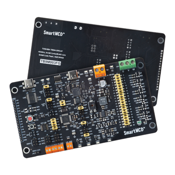
Summary of Contents for Mikroe SmartMCD TB9M003FG
- Page 1 S m a r t M C D ™ B O A R D U S E R M A N U A L...
- Page 2 Thank you for choosing MIKROE! We present you the ultimate solution for embedded development. Elegant on the surface, yet extremely powerful on the inside, we have designed it to inspire outstanding achievements. And now, it’s all yours. Enjoy premium.
-
Page 3: Table Of Contents
Table of contents Introduction 1. Key microcontroller features 2. MOS Stage FET Power 3. Power Supply 4. MCU Programming 5. Connectivity 6. Onboard Settings 7. SmartMCD™ board Peripherals 8. Current Monitoring... - Page 4 SmartMCD™ Board U S E R M A N U A L...
-
Page 5: Introduction
The SmartMCD™ board offers an advanced solution for The SmartMCD™ board includes an integrated inverter controlling brushless motors in automotive body systems. comprising six small-package, AEC-Q101 qualified Central to the SmartMCD™ board is the TB9M003FG (U1), MOSFETs (SSM6K809R) for efficient power management. a gate driver IC with a built-in MCU specifically designed for It also supports connection of external inverter versions automotive brushless DC (BLDC) motor applications, such... -
Page 6: Key Microcontroller Features
1. Key microcontroller features At its core, the SmartMCD™ board uses the TB9M003FG MCU. The TB9M003FG (U1) is Toshiba’s implementation of the 32-bit ARM® Cortex®-M0 core, capable of operating at a maximum frequency of 40MHz. It includes 64KB of code flash memory with ECC SEC/DED, allowing the programming of control methods and parameters tailored to specific motor and application requirements. -
Page 7: Mos Stage Fet Power
2. MOSFET Power Stage As mentioned, the SmartMCD™ board includes an integrated inverter comprising of six small-package, AEC-Q101 qualified MOSFETs (SSM6K809R - from Q2 to Q7) for efficient power management, connected via populated jumpers on the J5 header (1). These MOSFETs are driven by gate-signal outputs from the TB9M003FG (U1). -
Page 8: Power Supply
3. Power Supply The main power supply, which ranges from 6V to 18V (typically 12V), is provided to the TB9M003FG (U1) via the terminal. This power supply also feeds the entire inverter circuit and the step-down DC-DC converter, the MCP16331 (U3). The presence of active external power can be visually confirmed by a green PWR LED located near the connector. -
Page 9: Mcu Programming
4. MCU Programming The program/debug switch (SW1) allows you to select the debugging via the onboard CMSIS-DAP (U2). Alternatively, source for programming and debugging the TB9M003FG (U1). setting it to the EXT position allows for programming and When set to the INT position, it enables programming and debugging through the SWD connector (J4). - Page 10 4.2 Programming with an external programmer Figure 4.2: SmartMCD™ board connected with programmator* *Product images shown may represent a range of products or be for illustration purposes only, and may not be an exact representation of the product. The microcontroller can be programmed with an external programmer and supported software.
-
Page 11: Connectivity
5. Connectivity Serial communication with the TB9M003FG (U1) can be achieved through an external USB hosting device connected to the USB Type-C connector located in the upper left corner (CN3). The USB signals (USB-D_P, USB-D_N) are converted to UART serial data signals (UART-TX, UART-RX) by the USB-UART controller , the FT232RL (U9), enabling Figure 5.1: Actual details located in the upper left corner of the board. -
Page 12: Onboard Settings
6. Onboard Settings 6.1 Switches The start mode selection switch (SW2) is used to choose The slide switch (SW3) can be connected to either IO8 the activation mode of the TB9M003FG (U1). Upon resetting, or IO9 of the TB9M003FG (U1) by placing the appropriate the mode is determined based on the settings of the MD0 jumper on the J11 header (3). - Page 13 6.2 Headers, Jumpers and Connectors to IO11 pins of the TB9M003FG (U1), as well as to Some of the pins on the TB9M003FG (U1) are multiplexed, the 5V power supply and GND for testing purposes. with their assignments determined by the software configuration after startup.
- Page 14 6.3 Buttons The RST button generates a reset signal for the a jumper on either the IO7 or IO9 position. These jumper pins TB9M003FG(U1). The Start/Stop button (T2) is a push are used to connect the push-switch (T2) output (S/S) to IO7 switch that connects the switch’s output to GND when or IO9 of the TB9M003FG (U1).
- Page 15 4 11 Figure 6: Postion of Switches, Buttons, Headers, Jumpers, Connectors and LED Indicators SmartMCD™ Board U S E R M A N U A L...
-
Page 16: Smartmcd™ Board Peripherals
7. SmartMCD™ board Peripherals The external EEPROM memory (U8) can be connected to TB9M003FG (U1) by placing the corresponding jumper on the TB9M003FG (U1) via the header (J17) (1). By placing the TEMP-POT header (J16) (3). This TEMP signal can be jumpers on J17, the EEPROM’s SDO, SDI, SCK, CS, and WP used by the software to monitor the temperature and detect pins can be connected to IO3, IO4, IO5, IO6, and IO7 of the... -
Page 17: Current Monitoring
8. Current Monitoring Both sides of the inverter shunt resistor (R43) connected to the RSH pin (pin 27) and RSL pin (pin 28) of the TB9M003FG (U1). The voltage generated by the shunt resistor is amplified by the current-sensing amplifier built into the TB9M003FG (U1), and then output to the Overcurrent Detection Comparator (OCCMP) and Current Clamp Comparator (CLCMP). - Page 18 Figure 9: Brushless Motor with Hall Sensor connected on SmartMCD™ Board SmartMCD™ Board U S E R M A N U A L SmartMCD™ Board U S E R M A N U A L...
- Page 19 (including damages for loss of business profits and business information, business interruption or any other pecuniary loss) arising out of the use of this manual or product, even if MIKROE has been advised of the possibility of such damages. MIKROE reserves the right to change information contained in this manual at any time without prior notice, if necessary.
- Page 20 If you want to learn more about our products, please visit our website at www.mikroe.com If you are experiencing some problems with any of our products or just need additional information, please place your ticket at www.mikroe.com/support If you have any questions, comments or business proposals, do not hesitate to contact us at office@mikroe.com...
Need help?
Do you have a question about the SmartMCD TB9M003FG and is the answer not in the manual?
Questions and answers