Table of Contents
Advertisement
Quick Links
Table of Contents
DMX Click - User Manual ................................................................................................................................................... 1
Introduction ........................................................................................................................................................................... 2
The scope of this manual .................................................................................................................................................... 2
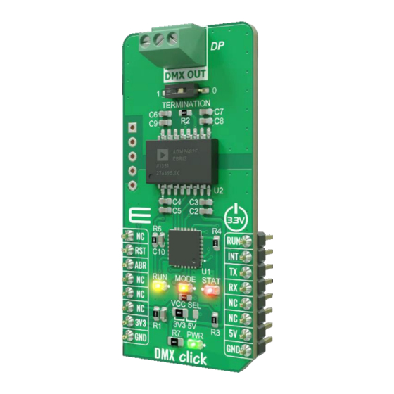
What is DMX Click? .......................................................................................................................................................... 2
Operating Modes ................................................................................................................................................................. 2
UART interface ................................................................................................................................................................... 3
Other considerations ........................................................................................................................................................... 3
Configuring the Click board™ ............................................................................................................................................ 3
MASTER/SLAVE selection ............................................................................................................................................... 3
(MASTER) RUN mode ...................................................................................................................................................... 4
(SLAVE) RUN mode .......................................................................................................................................................... 4
(MASTER/SLAVE) CFG mode ......................................................................................................................................... 5
DMX Start Code ................................................................................................................................................................. 5
Configuration commands ..................................................................................................................................................... 5
Commands structure ........................................................................................................................................................... 5
MASTER mode commands ................................................................................................................................................ 6
SLAVE mode commands.................................................................................................................................................... 7
Appendix:............................................................................................................................................................................... 9
DMX Click ABR setup and mode selection flow chart ...................................................................................................... 9
DMX Click - User Manual
[1]
Advertisement
Table of Contents

Subscribe to Our Youtube Channel
Related Manuals for Mikroe DMX Click

Summary of Contents for Mikroe DMX Click
-
Page 1: Table Of Contents
(MASTER/SLAVE) CFG mode ............................5 DMX Start Code ................................. 5 Configuration commands ..............................5 Commands structure ................................5 MASTER mode commands ..............................6 SLAVE mode commands..............................7 Appendix:....................................9 DMX Click ABR setup and mode selection flow chart ...................... 9... -
Page 2: Introduction
What is DMX Click? DMX Click is designed to accept the UART data stream on the RX pin and packs it into DMX frames, generated at the DMX output (3-pole screw terminal). Since the DMX 512-A protocol (DMX in the following text) is most commonly used to control stage lighting and other stage equipment (e.g. -
Page 3: Uart Interface
Other considerations The digital signal might deteriorate with a large number of SLAVE devices connected. However, DMX Click offers a lot of freedom and flexibility. The support for multiple DMX universes can be implemented within the lighting control application itself, while the actual number of connected SLAVE devices can be increased by using two or more DMX Clicks and using them to build so-called DMX Splitters and DMX Repeaters. -
Page 4: (Master) Run Mode
If the RUN pin is at a LOW logic level after the reset, the Click board™ will run as a DMX SLAVE. The MODE LED indicator will be turned OFF. The response message is: "SLAVE RDY" (terminated by the <cr><lf> sequence) If the RUN pin is at a HIGH logic level after the reset, the Click board™... -
Page 5: (Master/Slave) Cfg Mode
The DMX Start Code must always be transmitted in any DMX-compliant system. It will be transmitted automatically (MASTER mode) and it will be automatically inserted at the beginning of the received string (SLAVE mode). DMX Click is developed with lighting applications in mind and in this case, the Start Code should be always equal to 0 (Null Start Code, NSC). -
Page 6: Master Mode Commands
MASTER mode commands @FLEN,XXX XXX is the length of the DMX frame. The possible valid range is from od 001 to 512. Default: 512 A full DMX frame consists of 512 channels (512 bytes) plus one additional channel for the Start Code. However, it is not mandatory to transmit the entire DMX universe (512 channels). -
Page 7: Slave Mode Commands
XXX is the value of the Start Code. The possible valid range is from od 000 to 512. Default: 000 The Start Code has to be sent at the beginning of each DMX frame. However, its value is not mapped from the input buffer, it is set by this command, instead. - Page 8 Default: 008 The length of the DMX frame portion that will be received by the SLAVE device can be set by using this command. Channels beyond the received range will be disregarded. The possible valid range is from od 001 to 512. NOTE: If the parameters of the SADR and FLEN commands are set to channel addresses beyond the received DMX frame length, no error condition will be signaled.
-
Page 9: Appendix
Appendix: DMX Click ABR setup and mode selection flow chart...
Need help?
Do you have a question about the DMX Click and is the answer not in the manual?
Questions and answers