Advertisement
Quick Links
Bendix
of Bendix
Prior to installation or performing service to ABS
controllers always perform the following steps:
1. Inspect the vehicle for damage, chafing, etc. to current
ABS unit, hoses or wiring and adjust routing of replacement
installation as necessary.
2. Turn power off.
3. Drain the air pressure from all reservoirs.
4. Remove as much contamination as possible prior to
disconnecting electrical connections and air lines.
5. Note the original controller assembly mounting position on
the vehicle.
6. Follow all General Maintenance Precautions as found
below in these instructions.
REMOVING THE ORIGINAl cONTROllER
1. Disconnect the ECU connector and any modulator
connector from the controller.
2. Remove all air lines connected to the unit. (Use spray
lubricant on the swivel fittings of the delivery lines where
necessary before attempting to remove them.)
3. Remove the controller assembly from the vehicle by
removing the mounting bracket nuts or by rotating the
entire assembly counterclockwise from the tank mount.
4. Disconnect the ABS sensors and remove the existing
harness. Bendix requires that only Bendix wheel speed
sensors be used for Bendix ABS systems.
wHEEl SPEEd SENSOR REPlAcEMENT
Due to the critical safety function provided by any ABS
product, Bendix does not assume responsibility for antilock
system reliability or performance issues in situations where
substitute non-Bendix
ABS components, not supplied by
®
Bendix (for example, substituting a non-Bendix
sensor or modulator valve) are used on a vehicle equipped
with Bendix
ABS. In addition, use of alternate components
®
in place of genuine Bendix components could lead to rejection
of ABS warranty claims. See Bulletin TCH-013-009 for more
details.
INSPEcTION
Inspect the location selected for installation and clean as
necessary.
NOTE: Inspect all components, including the replacement
trailer ABS module, for any external damage, such as
cracked valve ports, electronic housings, etc. Any
components found to be damaged should not be installed
on the vehicle and must be replaced.
INSTAllATION
1. Position and secure the ABS unit in the original mounting
orientation: (The exhaust port must point straight down.)
Tank (nipple) mount unit - Install the nipple fitting into the
ABS module supply port. Then rotate the entire assembly
into the tank port until secure. Over-torquing of the tank
nipple could cause damage to the Module.
Installation Instructions
Trailer ABS Service Replacement Kit Intended for Service Replacement
®
A-18 controller Assemblies for 2S/1M Through 4S/2M Trailer ABS
®
wheel speed
®
S-1489 ©2007 Bendix Commercial Vehicle Systems LLC 2/07 Printed in U.S.A. All Rights Reserved.
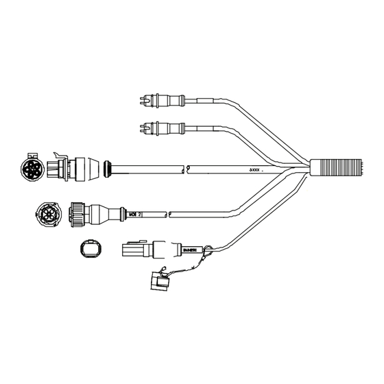
KIT cONTENTS
Item Description . . . . . . . . . . . . . . . . . . Qty.
1 . . ABS Power Harness (varies by kit). . . . . . . 1
2 . . Wheel Speed Sensor Harness . . . . . . . . . 2
3 . . Trailer ABS Module . . . . . . . . . . . . . . 1
4 . . Identification Label . . . . . . . . . . . . . . . 1
(not shown). . Service Data sheet. . . . . . . . . . 1
3
Cover
Release
Tab
FIGURE 1 - KIt (and optIonal dolly) componEnts
Frame (bracket) mount unit - Torque the mounting nuts to 180-
220 in-lbs.
2. Reconnect all air lines and plugs to the modulator-valve
assembly. Make certain that no thread sealing material enters
the valve. All air lines and fittings should be checked for leaks
prior to returning the vehicle to service.
3. Reconnect the ECU and sensor electrical connectors to the
unit. Slide the cover locking tab to gain access to the internal
connections. Apply a moderate amount of non-conductive
electrical grease to each connector pin before reconnecting.
1 (alt. style
harness)
1 (alt. style
harness)
B
A
D
2
4
E
C
Advertisement

Related Manuals for BENDIX K019713


Summary of Contents for BENDIX K019713
- Page 1 3. Reconnect the ECU and sensor electrical connectors to the Tank (nipple) mount unit - Install the nipple fitting into the unit. Slide the cover locking tab to gain access to the internal ABS module supply port. Then rotate the entire assembly connections. Apply a moderate amount of non-conductive into the tank port until secure. Over-torquing of the tank electrical grease to each connector pin before reconnecting. nipple could cause damage to the Module. S-1489 ©2007 Bendix Commercial Vehicle Systems LLC 2/07 Printed in U.S.A. All Rights Reserved.
- Page 2 5. following the vehicle manufacturer’s recommended procedures, deactivate the electrical system in a ABS wIRING manner that safely removes all electrical power from the The Bendix pigtail wiring harness and connectors are weather vehicle. resistant and sealed at the connector interface. 6. Never exceed manufacturer’s recommended pressures. 7. Never connect or disconnect a hose or line containing TROUBlESHOOTING pressure;...
- Page 3 Monday through Friday, 8:00 A.M. to 6:00 P.M. EST, and follow applications and systems. the instructions in the recorded message. 9. components with stripped threads or damaged parts Or, you may e-mail the Bendix technical assistance team at: should be replaced rather than repaired. do not attempt repairs requiring machining or welding unless specifically techteam@bendix.com.
- Page 4 • SAL & SAR (Additional Sensors) are connected to the 18-pin connector on the TABS6 ECU. • For lift axle applications, SAL & SAR (Additional Sensors) senses the wheels of the lift-able axle S-1489 ©2009 Bendix Commercial Vehicle Systems LLC 02/07 Printed in U.S.A. All Rights Reserved.
Need help?
Do you have a question about the K019713 and is the answer not in the manual?
Questions and answers