
Related Manuals for Smart Motor Devices SMSD-4.2LAN

Summary of Contents for Smart Motor Devices SMSD-4.2LAN
- Page 1 SMART MOTOR DEVICES https://smd.ee PROGRAMMABLE STEP MOTOR CONTROLLER SMSD-4.2LAN and SMSD-8.0LAN Manual Ver. 07 2019...
-
Page 2: Product Designation
Product designation Programmable step motor controller SMSD-4.2LAN is designed to operate with hybrid two or four-phase stepper motor with maximum current per phase up to 4.2Amp (SMSD-4.2LAN) or 8.0Amp (SMSD-8.0LAN). Three control modes are provided: programmable, analog control and position pulse control. The controller provides programming and control via USB or Ethernet. - Page 3 Construction SMSD-4.2LAN and SMSD-8.0LAN were designed to fit all the needed equipment on to a portable and efficient heat-sink mounted into a plastic case with DIN rail mount. SMSD-8.0LAN has a fan, mounted of the heat-sink, which provides active cooling.
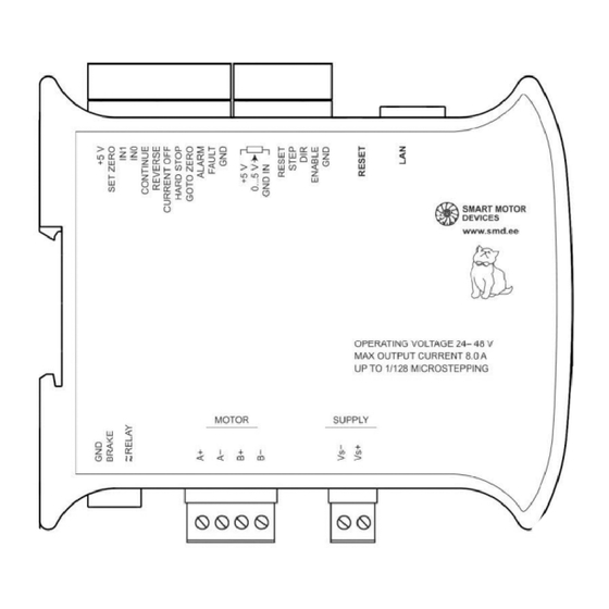
- Page 4 Table 2 Mark Designation Wiring Controller power supply Negative side of a power supply unit (24..48VDC) +VDD terminal Positive side of a power supply unit (24..48VDC) Phase А+ Part 6 «Stepper Phase А- Stepper motor leads motor connection screw terminal Phase B+ connection»...
- Page 5 Controller Controller +20VDC ALARM, STEP 100 Ohm FAULT Source of pulse signal 4..5VDC (24VDC) Fig. 4. Connection of output lines ALARM and FAULT. Outputs type - optoisolator output, max. Fig. 5. Connection of STEP signal voltage: 20VDC, max. current – 100mA Controller Controller R=3..4К...
-
Page 6: Controller Menu
Controller menu For the purposes of the controller adjusting the special controller menu is used (buttons MENU, UP and DOWN and 2-sign 7-segment display). Some parameters could also be set through the communication interface (using Ethernet or USB connection). 6.1 Usage of the controller menu To enter menu press and hold the button MENU till a sound signal (values at the display should start to blink). -
Page 7: Operation Order
6.3 Stepper motors list and numbers for the voltage motor control mode (menu item P1, P0 = Un): Value Max. current per Resistance per Inductance per Step angle Motor model SMSD-4.2LAN SMSD-8.0LAN phase, Amp phase, Ohm phase, mH No motor 1.33 1.33... - Page 8 controller) in an available range 0.1 – 4.2A (0.1 – 8.0A). The current motor control mode performs better torque and high rotation speed, but it is limited with a maximum microstepping division 1/16; Voltage control mode – performs smooth motion and provides microstepping division up to 1/128. However, rotation speed and torque are less in comparison with the current control mode.
- Page 9 a potentiometer or source of analog signal 0 – 5VDC. The motor motion can be started and stopped by pressing the START/STOP button, or by signal at the ENABLE input. The motor speed (or turning angle) is regulated by the internal potentiometer "SPEED", by external potentiometer or source of an analog signal 0-5VDC –...
- Page 10 Fig. 10 – Controller connection window Fig. 9. Main window of SMC-Program Please, chose a connection type (USB or Ethernet) and check (change if necessary) the connection parameters in the appeared window (Fig.10). The default parameters in the program correspond to default parameters of the controller. If the parameters were changed, new parameters should be set in the correspond fields.
- Page 11 Fig.13. Direct Control Mode window Fig.14. Program Load Mode window. The windows Direct Control Mode and Program Load Mode are intended for a motor control, executing programs assembling, loading to the controller and reading from the controller. At the right side of these windows command buttons are located, at the left side the sent commands and their executing results are shown.
-
Page 12: Manufacturer Information
1 pcs. 11. Manufacturer information Smart Motor Devices adheres to the line of continuous development and reserves the right to make changes and improvements in the design and software of the product without prior notice. The information contained in this manual is subject to change at any time and without prior notice.
Need help?
Do you have a question about the SMSD-4.2LAN and is the answer not in the manual?
Questions and answers