Table of Contents
Advertisement
Quick Links
MICROTECH
CONTROLLER
WITH MICROTECH 2310 I/O EXPANSION BOARD FOR
SINGLE COMPRESSOR WATER SOURCE HEAT PUMPS
• FOR MODELS SCH, SMH, SSH
©2024 DAIKIN APPLIED | (800) 432.1342
2300 UNIT
®
RY/PUMP
RY/PUMP
RY/FAN_EN
RY/FAN_EN
H7
H7
RY/FAN_HIGH
RY/FAN_HIGH
MT2300
MT2300
H1
H1
PART# 910384405
PART# 910384405
TB1
TB1
H4
H4
H8
H8
LED
LED FM
FM SP
SP RM
R R W2
W2 W1
W1 Y2
Y2 Y1
Y1 G G
C C
TB2
TB2
TB1
TB1
R R
W2
W2 W1
W1 Y2
Y2 Y1
Y1 G G
C C
LED
LED FM
FM SP
SP RM
H5
H5
PWM WSE
PWM
WSE GND
GND HGR
HGR GND
GND
AUX1 GND
AUX1
LEARN MORE AT DAIKINAPPLIED.COM
OPERATION MANUAL
OM 1364
H4
H4
H3
H3
10 10
9 9
8 8
7 7
6 6
5 5
4 4
3 3
2 2
1 1
RM GND
GND
E E
U U
TB3
TB3
E E
U U
RM GND
GND
H6
H6
GND AUX2
AUX2 GND
GND RV2
RV2 GND
GND COMP2
COMP2 GND
GND
AUGUST 2024
Advertisement
Table of Contents
Troubleshooting

Related Manuals for Microtech 2300

Summary of Contents for Microtech 2300
- Page 1 OPERATION MANUAL OM 1364 AUGUST 2024 MICROTECH 2300 UNIT ® CONTROLLER WITH MICROTECH 2310 I/O EXPANSION BOARD FOR SINGLE COMPRESSOR WATER SOURCE HEAT PUMPS RY/PUMP RY/PUMP RY/FAN_EN RY/FAN_EN 10 10 RY/FAN_HIGH RY/FAN_HIGH LED FM FM SP SP RM RM GND...
-
Page 2: Table Of Contents
For the most up-to-date product information, please go to www.DaikinApplied.com. ™® MicroTech, SiteLine, SmartSource, and Daikin Applied are trademarks or registered trademarks of Daikin Applied Americas Inc. The following are trademarks or registered trademarks of their respective companies: BACnet from American Society of Heating, Refrigerating and Air-Conditioning Engineers, Inc.;... -
Page 3: Safety Information
® modules see: DANGER • IM 955 - MicroTech III Wall Sensor For use with Microtech Danger indicates a hazardous situation, which will result in death or serious injury if not avoided. III Unit Controller • IM 1363 - MicroTech MT2300 Water Source Heat Pump... -
Page 4: Connections And Terminals
Input COMP1 Line1 Control Voltage COM/ LIVE x 3 Input COMP1 Line2 Control Voltage NEU/L2 Table 1: MicroTech 2300 unit controller connector and Daughter BACnet BACnet MS/TP Only Board terminal descriptions Table 2: MT2310 I/O board connectors and terminals Connector... -
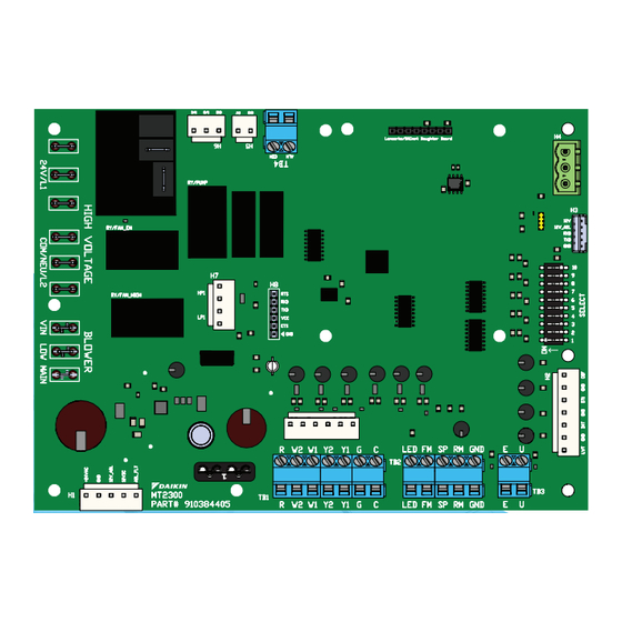
Page 5: Connections
CONNECTIONS AND TERMINALS MT2300 Unit Controller & MT2310 I/O Board Connections Figure 1: MT2300 and MT2310 Connections NOTE: Refer to Table 1 on page 4 for MT2300 controller terminal descriptions and Table 2 on page 4 for MT2310 I/O terminal descriptions RY/PUMP RY/PUMP... -
Page 6: Replacing Unit Controller
To help prevent damage during service, use static discharge wrist straps. Static discharge wrist straps are grounded to the heat pump chassis through a 1M ohm resistor. DAIKIN APPLIED MICROTECH 2300 UNIT CONTROLLER... - Page 7 CONFIGURATION DIP SWITCHES Table 3: MT2300 Main board DIP switch settings Table 4: MT2310 I/O expansion module DIP switch settings Switch Description Position Model/Options Switch Description Position Model/Options SW1 = OFF (0) Normal Operation Normal/Test Variable Speed Fan Row Mode Variable Fan Selection (1 to 16), used SW1 = ON (1)
-
Page 8: Functionality
A contact closure between terminals U and C on the MT2300 unit controller will place the unit into the DAIKIN APPLIED MICROTECH 2300 UNIT CONTROLLER... -
Page 9: Control Outputs
FUNCTIONALITy Control Outputs LED Indicators • The thermostat alarm output: Will be energized when When the unit controller or I/O boards are communicating a there are fault conditions presently active. Without any fault certain fault or mode, the LED indicator will flash a designated conditions active, the alarm output shall be de-energized. -
Page 10: Sequence Of Operation
The fan output is now determined by the determined by the MT2310 I/O expansion module configuration MT2310 I/O board configuration switches SW1-SW4 and the switch. When the room setpoint conditions are satisfied, the DAIKIN APPLIED MICROTECH 2300 UNIT CONTROLLER... - Page 11 SEqUENCE OF OPERATION 3-way valve will close and the fan will either shut off (fan switch sensing and by reducing the CFM by use of a humidistat in lieu of ”AUTO”) or continue to run (fan switch “ON” or configuration a thermostat.
-
Page 12: Unit Status
NOTICE The remote shutdown input (E) will suspend unit operation. Disconnect power Figure 8: Terminal “U” - Grounded for Unoccupied when servicing the unit/controller. U - Unoccupied E - Emer Shtdn Input Ground Ground DAIKIN APPLIED MICROTECH 2300 UNIT CONTROLLER... -
Page 13: Thermostat Inputs (G, Y1, Y2, W1, W2, W3, And W4)
SEqUENCE OF OPERATION Thermostat Inputs (G, Y1, Y2, W1, W2, W3, and W4) For units with both waterside economizer and hot gas reheat, the only thermostat inputs used during unoccupied operation are Y3, and W2/W3, which when energized will activate Cooling Mode or Heating Mode respectively. -
Page 14: Fault Modes
7. If the alarm condition remains active: — Compressor High Capacity is turned off — Compressor is immediately turned off, ignoring the Compressor Minimum ON timer — Compressor is disabled for heating, cooling, and DAIKIN APPLIED MICROTECH 2300 UNIT CONTROLLER... -
Page 15: Low Suction Temperature Fault Cooling
FAULT MODES dehumidification heating or cooling twice within 30 seconds (accomplished by user manipulation of the Heat/Cool/ Auto/Off switch on the — Electric heating can be used if it is available thermostat), an alarm reset equivalent to a tenant override button —... -
Page 16: Faults And Modes
(EWT) Sensor Failure of range" 8 Flash Fault Yellow Space Temp Sensor Fail Room Temp Sensor Room temp sensor read- Failure ing "out of range" 9 Flash Fault Yellow Return Air Temp Sensor Fail DAIKIN APPLIED MICROTECH 2300 UNIT CONTROLLER... - Page 17 TROUBLESHOOTING LED Activity Type Color Description Rapid Flash Mode Green Emergency Shutdown No Call for Heating / Cooling / 1 Flash Mode Green Dehumidification 2 Flash Mode Green Call for Cooling 3 Flash Mode Green Call for Heating 4 Flash Mode Green Call for Fan Only...
-
Page 18: Troubleshooting
H1-5 and 12VDC is not detected at H1-3 12V_ will be forced to high speed during this alarm and for a A2L input. Check connection at this terminal. minimum of 5 minutes after it has been resolved. DAIKIN APPLIED MICROTECH 2300 UNIT CONTROLLER... - Page 19 TROUBLESHOOTING A2L Error – Refrigerant Sensor Fail Leaving Water Temperature Sensor Failure LED Activity Type Color Description LED Activity Type Color Description A2L Mitigation – Refrigerant 5 Flash Fault Yellow Leaving Water Temp Sensor Fail Rapid Flash Mode Yellow Sensor Fail •...
-
Page 20: Troubleshooting The Water Source Heat Pump Unit
• Check blower assembly for dirt or faulty fan motor capacity. • Check for low refrigerant charge. • Check amp draw on blower assembly. • Check for proper water flow and delta T (°F). DAIKIN APPLIED MICROTECH 2300 UNIT CONTROLLER... -
Page 21: Start-Up
START-UP Start-Up Operation The MT2300 unit controller’s valve or pump request terminal [IV/ PR (H6)] is an output signal to external devices to allow water Thermostat Inputs flow as required by the heat pump. The IV/PR (H6) terminal follows compressor operation inversely if connected to the Waterside Economizer/ Dehumidification normally open terminal and simultaneously when connected to the normally closed terminal. -
Page 22: Electric Heat Controls
• Auxiliary Heat Stage #1 output energizes upon activation of “Heating – Stage #1. • Auxiliary Heat Stage #2 output energizes upon activation of Heating – Stage #4, except on units configured for both Waterside Economizer and Dehumidification. DAIKIN APPLIED MICROTECH 2300 UNIT CONTROLLER... -
Page 23: Heating Source Selection
HEATING SOURCE SELECTION Heating Source Selection Heating source selection provides a method to disable the compressor operation when in the heating mode. Baseboard SW7 Configuration Switch operation • OFF: Enables compressor operation in the heating mode. • ON: Disables compressor operation in the heating mode. When compressor operation is disabled in the heating mode and electric heat is available: •... -
Page 24: Fan Speed Selection
10-100%. When enabled, the network fan speed settings will override the local configuration switches. When the MT2310 status LED interval is yellow instead of Off, this indicates that the network is overriding the fan speed settings. DAIKIN APPLIED MICROTECH 2300 UNIT CONTROLLER... -
Page 25: Unit Options
UNIT OPTIONS Unit Options Waterside Economizer Application: The MT2300 controls the waterside economizer. Upon a call for economizer operation via TB1-3, HST on the MT2310 I/O expansion board, for units without hot gas reheat or Y1 on the MT2300 baseboard for units with hot gas reheat), the output to the 3-way diverting valve and the fan motor are energized, allowing water flow through the economizer coil and fan operation. -
Page 26: Dehumidification
• Humidistat and a Thermostat OR Digitally Adjustable Wall Sensor • Return air sensor Unit Control Settings • MT2310 I/O Expansion Module Jumper Settings: — SW7= ON (HGR Enabled) — SW8 = OFF (WSE Disabled) DAIKIN APPLIED MICROTECH 2300 UNIT CONTROLLER... - Page 27 DEHUMIDIFICATION Wiring Figure 16: Unit with WSE and HGR thermostat Wiring Diagram Figure 14: Thermostat and sensor combination hot gas Unit Thermostat reheat smart dehumidification wiring diagram R 24VAC Unit Thermostat Common R 24VAC Common Cool Stage 1 Cool Stage 2 Cool Stage 1 Cool Stage 3 Cool Stage 2...
- Page 28 TB3-1 TB3-2 TB1-3 Description Terminal Label Typical Wiring Terminal Label R (24VAC) 1 (ST) 2 (FM) 3 (SP) 4 (UTS) 5 (GND) 6 (FC) Description Sensor Digitally Adjustable Room Temperature Sensor (Part No. 910121754) DAIKIN APPLIED MICROTECH 2300 UNIT CONTROLLER...
-
Page 29: Humidistat Controlled Dehumidification
DEHUMIDIFICATION Humidistat Controlled Figure 19: Unit thermostat and humidistat combination - humidistat controlled dehumidification wiring diagram Dehumidification Unit Thermostat Application R 24VAC Similar to the simplified dehumidification option, this option also Common maximizes latent capacity by using a humidistat and thermostat. This option allows the room thermostat to control sensible cooling, while the independent humidistat controls room humidity Cool Stage 1... -
Page 30: Dehumidification Only
CFM. NOTICE Fan Performance section in catalog for unit size specific fan speeds. DAIKIN APPLIED MICROTECH 2300 UNIT CONTROLLER... -
Page 31: Controls
• Relays status of all vital unit functions controller and other ancillary components, see: The MT2300 unit controller with an • IM 955 - MicroTech III Wall Sensor For use with Microtech III Unit Controller optional communication module includes • IM 1363 - MicroTech MT2300 Water Source Heat Pump •... - Page 32 COMPLETE HVAC SYSTEM SOLUTIONS S E L F - C O N TA I N E D R O O F T O P S C O I L S C O N D E N S I N G U N I T S A I R H A N D L E R S | W AT E R - C O O L E D C H I L L E R S | A I R - C O O L E D C H I L L E R S M O D U L A R C E N T R A L P L A N T S | S I T E L I N E B U I L D I N G C O N T R O L S U N I T H E AT ER S | FA N CO I L S | A I R P U R I F I ER S | WAT ER S O U R C E H E AT P U M P S...
Need help?
Do you have a question about the 2300 and is the answer not in the manual?
Questions and answers