Advertisement
Quick Links
Advertisement

Related Manuals for Microtech e-GATE

Summary of Contents for Microtech e-GATE
- Page 1 INSTRUCTION MANUAL enquiries@microtechdesigns.com.au | microtechdesigns.com.au...
-
Page 2: Table Of Contents
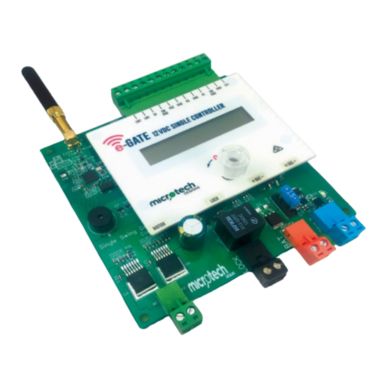
1 – Encoder 2 – Limit Switch 5 Wire Program 3 – Limit Switch 2 Wire Program 4 – End Stop Program 5 – Coding – e-Gate Single Set Up 6 – Coding e-Loop Set Up -Gate 12 gate control board Dual frequency 2.4 Gig and 433MHz... - Page 3 DISPLAY DISPLAY (Push Button / Dial) Specifications Incorporating SMD technology Solid state motor drive Multi frequency communication Single 12 motor drives up to 10 Amps Short circuit protection Reverse battery protection Built in solar charger Exceptionally low standby current 8 m/a...
-
Page 4: Menu Index
Menu Index Use the dial to scroll right to move forward in the menu Scroll left to go back through the menu Press PB to enter or exit any of the menus, or to select or alter any settings. SETUP MOTOR MAIN MENU SUB MENUS CODED DEVICES... - Page 5 RAMP MENU RAMP UP OPEN Allows you to change the ramp up open time. RAMP UP CLOSE Allows you to change the ramp up close time. RAMP DOWN OPEN Allows you to change the ramp down open time. RAMP DOWN CLOSE Allows you to change the ramp down close time.
-
Page 6: E-Gate Single Set Up
1. e-Gate Single Set Up – Encoder Note: Close stop must be fitted to motor arm for articulated arm style. For linear motor we use the fully extended internal stop. 1. Power up display, it will read ‘System Not Setup’ . Now press PB to enter set up menu. - Page 7 7. Once it reaches the end stop it will display ‘Set Open’ . Press and hold down PB or button 1 on a coded remote. Drive the gate to the open position, if you go too far you can rotate dial to ‘Drive Motor Close’ or use button 2 on a remote.
-
Page 8: Limit Switch 5 Wire Program
2. e-Gate Single Set Up – Limit Switch 5 Wire 1. Power up display, it will read ‘System Not Setup’ . Now press PB to enter set up menu ‘System Type’ . system not setup system not setup 12 9 volts 12 9 volts First display is ‘Encoder’... - Page 9 6. Rotate dial to ‘Setup System Press Button’ , now press PB and gate will close until it reaches the close limit. setup system setup system setting setting press button press button close close 7. Once gate reaches the close limit, the gate will open then close. opening opening closing...
-
Page 10: Limit Switch 2 Wire Program
3. e-Gate Single Set Up – Limit Switch 2 Wire 1. Power up display, it will read ‘System Not Setup’ . Now press PB to enter set up menu ‘System Type’ . system not setup system not setup 12 9 volts 12 9 volts First display is ‘Encoder’... - Page 11 6. Once gate reaches the close limit, the gate will open then close. opening opening closing closing 7. Once gate reaches the closed position, ‘Setup Complete’ will display, then after 2 seconds, the main screen will display. setup setup system closed system closed complete complete...
-
Page 12: End Stop Program
4. e-Gate Single Set Up – End Stop 1. Power up display, it will read ‘System Not Setup’ . Now press PB to enter set up menu ‘System Type’ . system not setup system not setup 12 9 volts 12 9 volts First display is ‘Encoder’... - Page 13 6. Once gate reaches the close limit, the gate will open then close. opening opening closing closing 7. Once gate reaches the closed position, ‘Setup Complete’ will display, then after 2 seconds, the main screen will display. setup setup system closed system closed complete complete...
-
Page 14: Coding - E-Gate Single Set Up
2. Now press the Remote button once and the e-Gate board will display ‘Confirm’ and the remote number (e.g. REM 2). Now press the Remote button a second time to confirm, and the e-Gate board will display ‘Coded’ and the remote number. -
Page 15: Coding E-Loop Set Up
6. Coding – e-Loop Set Up 1. Scroll to ‘Code Device. code device code device 2. Now place the e-Loop close to the antenna of the board then press and release PB. If pairing is successful, the screen will display ‘Loop (number) Paired’ . If not successful, ‘Code Learn’... - Page 16 enquiries@microtechdesigns.com.au | microtechdesigns.com.au...
Need help?
Do you have a question about the e-GATE and is the answer not in the manual?
Questions and answers