Table of Contents
Advertisement
Available languages
Available languages
ALLEN + ROTH and logo design are
trademarks or registered trademarks of LF,
LLC. All rights reserved.
Serial Number
Purchase Date
Thank you for purchasing this ALLEN + ROTH product.
Questions, problems or missing parts?
Before returning, contact us on:
866-439-9800, 8 a.m. - 8 p.m., EST, Monday - Sunday or ascs@lowes.com.
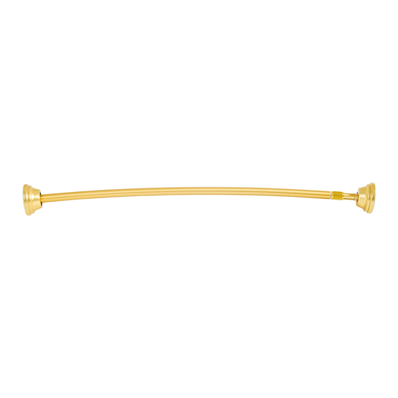
SG24695
ITEM #5138227/5138230/5138232/5138233/5277706
MODEL #SHLSNC01SN/SHLSNC01CH
44-IN TO 72-IN
SHOWER ROD
1
/SHLSNC01BR/SHLSNC01MB
/SHLSNC01SG
CURVED
Español p. 13
Advertisement
Chapters
Table of Contents

Related Manuals for Allen + Roth SHLSNC01SN


Summary of Contents for Allen + Roth SHLSNC01SN
- Page 1 SHOWER ROD Español p. 13 Serial Number Purchase Date Thank you for purchasing this ALLEN + ROTH product. Questions, problems or missing parts? Before returning, contact us on: 866-439-9800, 8 a.m. - 8 p.m., EST, Monday - Sunday or ascs@lowes.com.
-
Page 2: Table Of Contents
TABLE OF CONTENTS Package Contents..........................3 Hardware Contents..........................4 Safety Information..........................5 Preparation............................5 Tension Installation Instructions......................6 Permanent Installation Instructions....................... 8 Care and Maintenance ......................... 12 Troubleshooting............................. 12 Warranty..............................12 Replacement Parts List.......................... 12... -
Page 3: Package Contents
PACKAGE CONTENTS PART DESCRIPTION QUANTITY 1 in. Mounting Bracket ( Pre-assembled ) 7/8 in. Mounting Bracket ( Pre-assembled ) 1 in. End Cap ( Pre-assembled ) 7/8 in. End Cap ( Pre-assembled ) 1 in. Diameter Tube ( Pre-assembled ) 7/8 in. -
Page 4: Hardware Contents
HARDWARE CONTENTS (shown actual size) Large Hex Wrench Drywall Anchor Mounting Screw Qty. 4 Qty. 4 Qty. 1 Set Screw Small Hex Wrench Qty. 4 Qty. 2 ( 2 pcs pre-assembled ) ( 1 pc is extra part ) ( 2 pcs extra parts ) -
Page 5: Safety Information
SAFETY INFORMATION Please read and understand this entire manual before attempting to assemble, operate or install the product. WARNING • Make sure you are installing in a clean, dry and safe environment. • Do not stand on bath tub ledge. CAUTION •... -
Page 6: Tension Installation Instructions
TENSION INSTALLATION INSTRUCTIONS 1. Measure the distance of your desired location and record the length. 2. Place the rod on a flat surface and unscrew the tightening sleeve (L) until the threaded collar (K) is fully disengaged. 3. Extend the rod to the length that was recorded in step 1. - Page 7 TENSION INSTALLATION INSTRUCTIONS 4. Using the small hex wrench (DD), tighten the set screws (J) until the threaded collar (K) can't move. Do not overtighten. Hardware Used Small Hex Wrench 5. Thread the tightening sleeve (L) over the threaded collar (K) until the tightening sleeve (L) contacts the large 1 in.
-
Page 8: Permanent Installation Instructions
PERMANENT INSTALLATION INSTRUCTIONS 1. Disassemble rod and remove the tightening sleeve (L) and threaded collar (K). 2. Reassemble the rod and position the plastic sleeve (M) against near the junction of the large and small tubes (E & F). 3. Rotate all end caps (C&D) to the left and separate backwards from all mounting brackets (A&B). - Page 9 PERMANENT INSTALLATION INSTRUCTIONS 4. Place the rod in your desired location and extend until both mounting brackets (A&B) touch the wall. 5. Use a pencil to mark the hole locations through the mounting bracket (A). Repeat this step on the other side. 6.
- Page 10 PERMANENT INSTALLATION INSTRUCTIONS 7. Insert drywall anchor (BB) into the marked positions until flush with the wall. Repeat this step on the other side. Hardware Used Drywall Anchor 8. Insert mounting screws (AA) through the mounting bracket (A) into drywall anchors. Repeat this step on the other side.
- Page 11 PERMANENT INSTALLATION INSTRUCTIONS 10. Push the end cap (C) back into place at the end. Note that the concave point on the end cap (C) line up with the open slot in the mounting bracket (A), then rotate the end cap (C) to the right to lock it in place.
-
Page 12: Care And Maintenance
CARE AND MAINTENANCE • Wipe clean with damp cloth. TROUBLESHOOTING PROBLEM POSSIBLE CAUSE CORRECTIVE ACTION 1. Use large hex wrench to lock the Tension mounting is 1. Not locking tightly between mounting bracket screw more used, but the product mounting bracket and tube. tighter. - Page 13 MODELO #SHLSNC01SN/SHLSNC01CH /SHLSNC01BR/SHLSNC01MB /SHLSNC01SG CORTINERO PARA DUCHA CURVO DE ALLEN + ROTH y el diseño del logotipo son marcas comerciales o marcas registradas de 111.76 CM A 182.88 CM LF, LLC. Todos los derechos reservados. English p. 1 Nú mero de serie Fecha de compra Gracias por comprar este producto ALLEN + ROTH.
- Page 14 Í NDICE Contenido del paquete........................15 Aditamentos............................16 Informació n de seguridad........................17 Preparació n............................17 Instrucciones de instalació n de tensió n....................18 Instrucciones de instalació n permanente.................... 20 Cuidado y mantenimiento........................24 Solució n de problemas........................24 Garantí a.............................. 24 Lista de piezas de repuesto........................
-
Page 15: Contenido Del Paquete
CONTENIDO DEL PAQUETE PIEZ A DESCRIPCIÓ N CANTIDAD Soporte de montaje de 2.54 cm (preensamblado) Soporte de montaje de 2.22 cm (preensamblado) Tapa para extremo de 2.54 cm (preensamblado) Tapa para extremo de 2.22 cm (preensamblado) Tubo de 2.54 cm de diá metro (preensamblado) Tubo de 2.22 cm de diá... -
Page 16: Aditamentos
ADITAMENTOS (se muestran en tamaño real) Ancla de expansió n Tornillo de montaje Llave hexagonal grande para panel de yeso Cant. 4 Cant. 4 Cant. 1 Tornillo de fijació n Llave hexagonal pequeña Cant. 4 Cant. 2 ( 2 unidades está n preensambladas ) ( 1 unidad es una pieza adicional ) ( 2 piezas adicionales ) -
Page 17: Informació N De Seguridad
INFORMACIÓ N DE SEGURIDAD Lea y comprenda completamente este manual antes de intentar ensamblar, usar o instalar el producto. ADVERTENCIA • Asegú rese de que está realizando la instalació n en un entorno limpio, seco y seguro. • No se pare sobre el borde de la bañera. PRECAUCIÓ... -
Page 18: Instrucciones De Instalació N De Tensió N
INSTRUCCIONES DE INSTALACIÓ N DE TENSIÓ N 1. Mida la distancia de su ubicació n deseada y registre el largo. 2. Coloque la varilla sobre una superficie plana y desenrosque el manguito de ajuste (L) hasta que el anillo roscado (K) esté completamente desenganchado. - Page 19 INSTRUCCIONES DE INSTALACIÓ N DE TENSIÓ N 4. Con la llave hexagonal pequeña (DD), apriete los tornillos de fijació n (J) hasta que el anillo roscado (K) no pueda moverse. No apriete demasiado. Aditamentos utiliz ados Llave hexagonal pequeña 5. Enrosque el manguito de ajuste (L) sobre el anillo roscado (K) hasta que el manguito de ajuste (L) entre en contacto con el tubo grande de 2.54 cm de diá...
-
Page 20: Instrucciones De Instalació N Permanente
INSTRUCCIONES DE INSTALACIÓ N PERMANENTE 1. Desarme la varilla y retire el manguito de ajuste (L) y el anillo roscado (K). 2. V uelva a ensamblar la varilla y coloque el manguito de plá stico (M) cerca de la unió n de los tubos grande y pequeño (E y F). - Page 21 INSTRUCCIONES DE INSTALACIÓ N PERMANENTE 4. Coloque la varilla en la ubicació n desead a y extié ndala hasta que ambos soportes de montaje (A y B) toquen la pared. 5. Utilice un lá piz para marcar las ubicaciones de los orificios a travé...
- Page 22 INSTRUCCIONES DE INSTALACIÓ N PERMANENTE 7. Inserte el ancla de expansió n para panel de yeso (BB) en las posiciones marcadas hasta que quede al ras con la pared. Repita este paso en el otro lado. Aditamentos utiliz ados Ancla de expansió n para panel de yeso 8.
- Page 23 INSTRUCCIONES DE INSTALACIÓ N PERMANENTE 10. Empuje la tapa del extremo (C) nuevamente en su lugar en el extremo. Tenga en cuenta que el punto có ncavo de la tapa para el extremo (C) se alinea con la ranura abierta en el soporte de montaje (A), luego gire la tapa para el extremo (C) hacia la derecha para fijarla en su lugar.
-
Page 24: Cuidado Y Mantenimiento
CUIDADO Y MANTENIMIENTO • Limpie con un paño h ú medo. SOLUCIÓ N DE PROBLEMAS PROBLEMA CAUSA POSIBLE ACCIÓ N CORRECTIVA Se utilizó el montaje de 1. No hay un bloqueo firme entre 1. Utilice una llave hexagonal tensió n, pero el el soporte de montaje y el tubo.
Need help?
Do you have a question about the SHLSNC01SN and is the answer not in the manual?
Questions and answers
I dont have piece K for my cured shower rod, Allen roth curved shower rod assemby parts SHLSNC01SN
Part K, the "Anillo roscado" (threaded ring), is pre-assembled in the Allen + Roth curved shower rod assembly SHLSNC01SN. It should already be included in the package contents.
This answer is automatically generated