Table of Contents

Related Manuals for SDI LNFR-100A


Summary of Contents for SDI LNFR-100A
- Page 1 PECTRA YNAMICS LNFR-100A OISE REQUENCY EFERENCE PERATING ANUAL SPECTRADYNAMICS, INC • 1849 Cherry St. Unit 2. • Louisville, CO 80027 Phone: (303) 665-1852 • Fax: (303) 604-6088 www.spectradynamics.com...
- Page 2 LNFR-100A Option 5 & 10 MHz, Low Noise Frequency Reference Operating Manual Copyright © 2017 SpectraDynamics, Inc. All rights reserved. LNFR-100A Option 5 & 10 MHz: R00-2017/MD...
-
Page 3: Table Of Contents
Contents Introduction ……………………………………………………………………..1 Safety and preparation for use ………………………………..……….…….. 2 2.1 Electrical ……………….…………………………………………….……. 2 2.2 Instrument ……..…………….………………………………….….…….. 3 Front panel description …….…………………………………………….…… 4 Back panel description ………………………………………………….……. 5 Installation ……………………………………………………………….…….. 6 Operation ……………………………………………………………………… Troubleshooting ………………………………………………………………. 8 Specifications …………………………………………………………………. 10 Warranty and service …………………………………………………………... -
Page 5: Introduction
1.0 Introduction The LNFR-100A is an ultra-low noise 5 MHz and 10 MHz source. It contains a ultra low noise 5 MHz oscillator. The output at 10 MHz, is obtained by doubling the signal from the 5 MHz oscillator. All outputs to the front panel are buffered with low noise isolation amplifiers. -
Page 6: Safety And Preparation For Use
2.0 Safety and Preparation for Use The LNFR-100A was designed for indoor use only and is not intended for operation outdoors or in a wet environment. The instrument may be mounted in a standard 19-inch instrumentation rack or may be used on a laboratory bench. -
Page 7: Instrument
If an external reference signal is used please make sure that the level is in the range of +7 dBm and +15 dBm. If a DC level will be used for tuning the LNFR-100A make sure that the DC signal level does not exceed the limits for the device of +/- 5 VDC. -
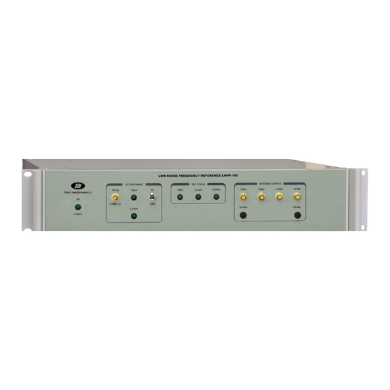
Page 8: Front Panel Description
DC / 5 MHz Switch The switch is used to select the type of signal applied to the LNFR-100A. In the DC position the tuning signal should have a DC level in the range of +/- 5V. In the 5 MHz position, the tuning signal should have a frequency of 5MHz +/- 1Hz and a level in the range of +7 to +15 dBm. -
Page 9: Back Panel Description
4.0 Back Panel AC Power The LNFR-100A power switch, fuse holder and voltage selector are all contained on the power entry module located on the rear panel. Page 5... -
Page 10: Installation
The LNFR-100A ships with a standard North American or European IEC power cord. The instrument may be mounted in a standard 19-inch instrument rack or may be operated on a laboratory bench. -
Page 11: Operation
Reverse RF or DC power should not be applied to the output ports. The LNFR-100A may be used as a free running low noise frequency source or can be locked to an external reference signal. To use the LNFR-100A without locking it to an external reference, or in free running mode, simply turn the switch, located on the front panel, to the DC position. -
Page 12: Troubleshooting
Disconnect the power cord and the fuse holder in the power entry module. Check the main AC power fuse and power cord. If the fuse is blown replace with same type and rating. Please contact SDI if the fuse blows again or if the event that caused the fuse to blow is not known. - Page 13 7.0 Troubleshooting Mechanical Tuning Mechanical tuning is available to compensate for the long-term frequency drift of the internal oscillators. Only fully qualified service personnel should perform this procedure. No signal should be connected to the tuning port when performing mechanical tuning! 5 MHz Tuning: Set the switch to the DC position and remove the top cover of the LNFR-100.
-
Page 14: Specifications
8.0 Specifications PARAMETER CONDITIONS UNITS Output Power Level 5 MHz Output Power Level 10 MHz Electrical Tuning Range 5 MHz, 10 MHz, +/- 2 E-7 Tuning Port Voltage +/- 5 Temperature Stability @ 5 MHz, 0 – 60 C +/-5 E-9 +/- 1 E-8 Phase Noise measured 1 Hz... -
Page 15: Warranty And Service
SDI’s option, any product not meeting the said specifications. This warranty shall be in effect for one (1) year from the date a LNFR-100A is sold by SDI. SDI makes no other warranty, express or implied, and makes no warranty of the fitness for any particular purpose.
Need help?
Do you have a question about the LNFR-100A and is the answer not in the manual?
Questions and answers