Advertisement
Quick Links
Advertisement

Subscribe to Our Youtube Channel
Related Manuals for SDI NMSC-2


Summary of Contents for SDI NMSC-2
- Page 1 NMSC-2 Quick Start Guide...
- Page 2 Table of Contents Introduction………...……...………………………………………….. Hardware Installation…...……………………………………………. Quick Start Guide…………………………………………………….. Sample results ………………………………………………………..
-
Page 3: Introduction
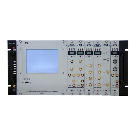
5U X 19” X 16”. The instrument crate is included with the purchase of a Noise Measurement System Controller (NMSC). The NMSC-2 module contains a dual-channel spectrum analyzer. Dual channel cross-correlation measurement techniques can be used to measure signals that are lower than the system noise floor. -
Page 4: Hardware Installation
The back of the NMS Instrument Crate has two circular power connectors and LED indicators. The 14 pin connector delivers power to the NIM Modules while the 24 pin connector delivers power to the NMSC-2 controller. NMS RACKMOUNT INSTALLATION The NMS is designed to be rack mounted on standard 19" wide racks. The NMS Crate has 5U non-removal rack mount handles, while the external power supply has removable 2U rack handles. - Page 5 The Master Power Switch is located on the rear of the DC Power Module. CAUTION! DO NOT TURN OFF THE MASTER SWITCH UNLESS POWER TO THE NMSC-2 CONTROLLER AND THE NMS CRATE IS TURNED OFF. Turning this switch off will immediately cut power to the computer and the NMS Instrument Crate.
- Page 6 Hardware Installation NMSC MODULE INSTALLATION The NMS Controller is the heart of the noise measurement system. It is composed of a Pentium Dual Core based computer and a high-speed digitizer. It also has a resistive touch screen LCD. The Windows XP operating system was chosen because of its popularity.
-
Page 7: Quick Start Guide
NMSC POWER ON The NMSC-2 Controller has a POWER ON button on the front panel just below the screen. The NMSC POWER ON button only powers the NMSC controller and will not turn on power to the instrument crate. To apply power to any of the detectors you must turn on the Chassis DC POWER SWITCH located on the lower left hand corner of the chassis. - Page 8 Quick Start Guide The NMSC software will load to an initial screen with the name of the software and the company name. Once the system initializes it will change to the FFT measurement screen shown below.
- Page 9 Quick Start Guide ASSIGN THE NOISE DETECTORS TO A MEASUREMENT CHANNEL On the bottom of the FFT screen there is a series of tabs that access different control pages. Select the tab marked Detector to access the Noise Detector Setup Page.
- Page 10 Quick Start Guide Press the SCAN button. This will scan the chassis for available noise detectors. The model number and frequency range of the detectors should appear in the corresponding bin position on the screen. Use the drop down selection button to select a Noise detector to be used on Channel 1 of the system and if more than one detector is installed you may select the Noise detector that is to be assigned to Channel 2 of the system.
- Page 11 Quick Start Guide SETUP ND-1 DETECTORS The Noise Detector software configuration is set by pressing the CH 1 DETECTOR or CH 2 DETECTOR button, this will bring up the Noise Detector setup window shown below. The ND-1 Noise Detector setup window has three pages that are accessed by pressing the NEXT button.
- Page 12 Quick Start Guide PLL SETTINGS The third page shows the phase lock controls of the selected noise detector. The PLL parameters can be selected and the PLL can be activated or turned off. The PLL parameters are set from the user supplied information such as the PLL locking bandwidth, the sensitivity of the tuning port and the sensitivity of the mixer.
- Page 13 Quick Start Guide Below is a block diagram of a typical single channel phase noise measurement for two oscillators. REF OSC Noise Detector NMSC Channel 1 DUT OSC Optional PRI FILTER USE DETECTOR SETUP WINDOW AGAIN Once the RF signals are connected to the noise detector you may want to open the DETECTOR SETUP window again to adjust the PLL parameters or check the IF output voltage or the mixer voltage.
- Page 14 Quick Start Guide SET INPUT RANGE OF THE NMSC-2 Once the RF signals are adjusted for your particular measurement. Select the SETUP tab on the bottom of the FFT screen to adjust the input range of the digitizer in the controller.
- Page 15 The RANGE button will do a single range finding operation. SELECT FREQUENCY RANGE FOR THE MEASUREMENT The NMSC-2 built in analyzer can perform Fast Fourier analysis from 0.1Hz to 40MHz. Click on the SET FREQ button to access the frequency selection dialog window.
- Page 16 Quick Start Guide SELECT AVERAGING PARAMETERS The FFT analysis for the chosen frequency range is done in multiple spans. One span will typically cover one decade in frequency. Different number of averages can be chosen for the different frequency spans using the SET AVERAGE function, which will bring up the NUMBER OF AVERAGES window.
- Page 17 Quick Start Guide The RMS averaging function can be turned on or off using the RMS ON/OFF button. The type of FFT window can be selected by clicking on the WINDOW button. There is also a button that allows you to select between a linear weighted average and an exponentially weighted average.
- Page 18 Software Overview The Measurement System Software has two modes of operation FFT mode and SCOPE mode. In FFT mode the noise signals are analyzed in the frequency domain by digitizing the signals, applying a window function on the digitized data and then performing an FFT on the data.
-
Page 19: Sample Results
Sample Results A sample of the plots produced by the measurement system software is shown below. The plot contains the result of a noise floor measurement using the ND-3-NM Noise Detector. The carrier frequency was 9200 MHz and the amplitude of the signals was 10 dBm.
Need help?
Do you have a question about the NMSC-2 and is the answer not in the manual?
Questions and answers