Table of Contents
Advertisement
Quick Links
Advertisement
Table of Contents

Related Manuals for Novus NV4000i


Summary of Contents for Novus NV4000i
-
Page 3: Table Of Contents
Table of Contents Foreword .........................1 Important Marks ......................2 Safety Instruction ......................3 Control System ....................... 7 Appearance ......................7 Control Panel ......................8 Engine Switch ......................8 Oil Alert Indicator (Yellow) ................... 8 Overload Indicator (Red) ..................9 AC Indicator (Green) ....................10 ECO Switch ...................... - Page 4 Muffler Cover ....................... 28 Storage .......................... 29 Pump out fuel ......................29 Engine ........................29 Trouble Shooting ......................30 The Engine Cannot Be Started................30 No voltage Output From Generator ..............30 Specification ......................... 31 Circuit Diagram ......................32 Parts List ........................33 Wearing Parts ........................33 2-Year Limited Warranty .....................
-
Page 5: Foreword
Foreword Thank you for purchasing our gasoline generator sets. ●The copyright belongs to Novus Performance Products LLC, who reserves all the right. ●Without the written permission of Novus Performance Products LLC, any form of copy, transmission, distribution and storage of this manual is forbidden strictly. -
Page 6: Important Marks
Important Marks Your and others’ personal and property safety is very important. Please read the Safety Warning with “ ”, and the Safety Tips with “NOTICE”. The details are listed below: DANGER indicates a hazardous situation which, if not avoided, will result in death or serious injury. -
Page 7: Safety Instruction
Safety Instruction Before operating the generator, please read and understand this manual. It can avoid the accidents by familiarizing yourself with the safe operation procedure of the generator. The emission gas is poisonous Do not use this generator in confined places. It ... - Page 8 The engine and muffler will be heated Keep the generator out of the reach of pedestrians and children. When running the generator, don’t put any flammable material near to the exhaust vent. Keep the clearance more than 1 meter between ...
- Page 9 Connection Notice Do not connect this generator to mains electricity. Do not connect this generator to other generators. Connect to household power supply When connecting the generator to household power supply as a backup power, it should be operated by an electrician of other professional person. After connecting the load to generator, check and ensure the safety and reliability.
- Page 10 Others Keep the blowhole of fan cover, muffler and engine bottom clear and free of debris, mud, water, etc. If these blowholes blocked, engine, inverter or motor parts may be damaged. Keep it far from other items, when moving, storing or using the generator. If oil leak occurs, it could be harmful to the engine, or other property.
-
Page 11: Control System
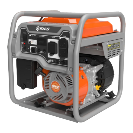
Control System Appearance Control Panel Motor Cover 13. Dump Valve Frame Muffler 14. Fuel Meter Air Filter Spark Eliminator 15. Fuel Tank Recoil Starter 10. Carburetor 16. Fuel Cap Drain Bolt 11. Choke Valve Cable 17. Defender Oil Dipstick 12. Fuel Switch... -
Page 12: Control Panel
Control Panel WM4000i 120V 60Hz 1. Engine Switch 2. AC Overload Reset 3. ECO-Mode Switch 4. CO Sensor Light 5. Low Oil 6. Overload 7. Output 8. 2x 5V USB Ports 9. 3 in 1 Meter 10, 11:Parallel Ports 1 2 3 4 5 6 7 8 9 10 11 12 13 12. -
Page 13: Overload Indicator (Red)
lube oil is insufficient. Refill with oil and try to start the engine again. Overload Indicator (Red) Overload indicator lights up when the generator has detected that the output of the connected electrical equipment has been overloaded, causing the inverter to overheat, or the AC voltage to rise. In the meantime, AC protector works and stops the generator from generating power to protect it and its connected electrical equipment. -
Page 14: Ac Indicator (Green)
If the D/C breaker is OFF, try to reduce the device’s load to within generator’s rated output, and if the breaker is still OFF, stop the machine immediately and consult the NOVUS seller. Grounding Terminal The grounding terminal① should be connected to... -
Page 15: Co Sensor
grounding wire to avoid electric shock. When the electric device is grounded, the generator must be grounded, too. Connection of the generator to a building’s electrical system, as applicable. These instructions shall include the need for a transfer switch installed by licensed electricians who are approved by the authority having jurisdiction. - Page 16 The YELLOW light will flash for at least five minutes after a fault. When the yellow light turns on, the generator cannot be started and must be repaired immediately. A CO sensor fault can only be diagnosed and repaired by an authorized NOVUS service center.
-
Page 17: Parallel Output Terminal
Parallel Output Terminal Parallel output terminals ① can be used by connecting two units of NV4000i through the parallel control box (rated output for these two units is 6.6KVA). The related operation and information will be introduced in details in the... -
Page 18: Checking Before Operation
Checking Before Operation NOTE Checking before each operation Be sure to perform a pre-use check before each use. BEFORE STARTING THE GENERATOR Verify that: • Inspect the generator and any attachments for damage, such as the fuel system, outlets, exhaust system, wiring, and extension cords. •... -
Page 19: Engine Oil
After refueling, the spilled fuel should be wiped clean immediately. Unleaded gasoline is required, as leaded gasoline will damage the internal engine part seriously. Confirm the tank have enough fuel. Recommended fuel: unleaded gasoline Fuel capacity total: 2.4 gal. F FF(FULL)... -
Page 20: Operation
Operation Forbidden to use the engine in a confined place, the exhaust gas will make people unconsciousness or even death in short time. Operate the engine in a well-ventilated area. The generator was delivered without oil injection. Do not start the generator without filling it with sufficient oil. - Page 21 2. Put the engine switch to “ON” position a. Open fuel system b. Open ignition system c. Choke off ,the generator stay in cool working state. Tips: While starting the engine, no need to close the choke, just put the generator switch to “ON” position 3.
-
Page 22: Engine Stop
When the environment temperature is lower than 0 degree (32 degrees F), and engine RPM is 3600, ECO is OFF, the warm-up time is less than 5 min. When the environment temperature is lower than 5 degree (41 degree F), and engine RPM is 3600, and ECO is ON, the warm-up time is less than 3 min. - Page 23 Make sure the rated load current is within the range of rated current for socket. Attention : If the electrical equipment requires grounding, the generator must be grounded. Start the engine. Make sure the AC light is on. Insert the plug into the socket. 4 Open the Electrical Equipment.
-
Page 24: Ac Parallel Operation
Two generators’ ECO switch should be both in the same position for parallel operation. Using special cable set to Parallel two NV4000i. Starting the engine, make sure the output indicator (green light) of each generator is on. - Page 25 is on continuously, it may damage the generator, and if the overload indicator light (red) keep flashing, it may shorten the life of machine. The limited working time for maximum power is 30 minutes.
-
Page 26: Applied Range
Applied Range Make sure the total load is within the rated load of the generator before using, otherwise the generator may be damaged. 0.4-0.75 Power Factor 0.8-0.95 (efficiency 0.85) Rated Voltage 12v 4000i ~3500W ~2800W ~1400W Rated Current 8.3A Remark ~ stands for ‘do not exceed’. - Page 27 Never overload the generator. The total power of loading device should not exceed rated power of generator, otherwise the generator will be damaged. When using this generator to supply power to precision instrument, electronic controller, PC, EC and microcomputer, etc., please keep a sufficient distance between the equipment and the generator to prevent electromagnetic interference.
-
Page 28: Maintenance
Users should operate safely. Periodic checking, adjustment and lubrication can make sure the generator performs more safely and efficiently. The contents below are the main checking items. If you are not familiar with the maintenance, please ask NOVUS dealers for help. Maintenance Schedule Please stop the engine before maintaining. - Page 29 *1. The first engine oil replacement should be made within the first month of use or after it works for 20 hours. *2. The air cleaner should be cleaned more frequently when used in the damp and dusty place. NOVUS dealers. ★ These items should be maintained by...
-
Page 30: Checking Spark Plug
Install Spark plug Turning around the spark plug to 1/4-1/2 circle to the assigned position. Install spark plug cap and cover. Adjusting Carburetor Adjustment of the Carburetor should be done by well-trained person with professional facilities from Novus dealer because the... -
Page 31: Replacing Engine Oil
Carburetor is an important part for generator. Replacing Engine oil Never drain engine oil immediately after turning it off because the engine oil is at high temperature to avoid any burns. ①Oil dipstick ②Seal ③Seal gasket Drain bolt 1. Place the generator horizontally at first, then start the generator and keep it running some minutes, stop... -
Page 32: Muffler Cover
2. Clean the air filter with dissolvent and dry it 3. Add oil to the foam filter and squeeze out excessive oil. The filter should be wet but not dripping oil. 4. Put the filter into air cleaner Notice Make filter cling with air cleaner without any gap Please do not start generator without the air cleaner to avoid any damage on cylinder and other parts on engine... -
Page 33: Storage
Storage You need do the following jobs if you plan to store machine for a long time. Pump out fuel Set the switch to OFF position. Remove the fuel filter and take out all the fuel. Read the Instruction at first and clean the fuel with a soft and dry cloth because fuel is volatile and poisonous. -
Page 34: Trouble Shooting
There is carbon deposit or wet in Spark plug, then clean it and dry it. Ignition system problem, please contact Novus dealer. No voltage Output From Generator AC indication lamp(Green)turned off, then turn off engine, and re-start. -
Page 35: Specification
Specification... -
Page 36: Circuit Diagram
Circuit Diagram NV4000i 120V 60Hz... -
Page 37: Parts List
Parts List Wearing Parts Part. NO. DESCRIPTION 360800010 CYLINDER HEAD GASKET 1101400006-0001 CARBURETOR GASKET 2204700003-0001 INTAKE PORT GASKET 1202000009-0001 SPARK PLUG 1200800037-0001 EXHAUST PORT GASKET 1900100009-0001 CYLINDER HEAD GASKET 1900200006-0001 AIR FILTER FOAM ELEMENT 1807900085-0001 CARBURETOR 1901000005-0001 CRANKCASE GASKET 1903700036-0001 OIL SEAL... - Page 38 Panel Components Part. NO. Description 2205100007-0001 Switch 2216700001-0001 Indicator Light Assembly 2205200002-0001 Push Button Switch 2216700007-0001 Red /Yellow Indicator 2205100002-0001 Switch 2200700009-0001 Digital Timer 2200400026-0001 DC Socket 2200400005 Combination Socket 2200400027-0001 Socket...
- Page 39 1.10 2201200004-0001 Ground Wire Pillar 1.11 2201100072-0001 Thermal Protector 1.12 2201100019-0001 Thermal Protector 1.13 2200400028-0001 Socket 1.14 ………………. Panel Iron Plate 1.15 2201600002-0001 Rectifier Bridge 1.16 2210500020-0001 CO Alarm Controller 1.17 2202300001-0000 Wiring Harness Sleeve 1.18 360040023 Screw GB/T6177.1/M4 360300005 Screw GB/T5789/M6*12 3411100011-0001 Washer...
- Page 40 Frame Components Part. NO. Description 2432700299-0001 Frame 1802500009-0001 Fuel Tank Cushion 360300005 Flange Bolt GB/T5789/M6*12 2434100004-0001 Damping Foot 360040009 Flange Nut M8(GB/T6177.1) 1600600010-0006 Wind Shield 2434300008-0001 Damping Stand 2434300009-0001 Damping Stand 360300104 Flange Bolt M8*35(GB/T5789) 2449100018-0002 Engine Bracket...
- Page 41 Fuel Cock Components Part. NO. Description 3000400001-0001 Cable Round Head Screw 360410008 M4*10(GB/T818) 1814800001-0001 Fuel Cock Knob 1814500001-0001 Fuel Cock Bracket Flange Screw M6*12 360300005 (GB/T5789) 1803500002-0000 Fuel Cock Flange Screw 360220026 GB/T16674.1/M6*16...
- Page 42 Fuel Tank Components Part. NO. Description 1800100400-0002 Fuel Tank 1812900002-0001 Tipping Valve Assembly 1803400001-0001 Fuel Guage Clamp 360420003 Screw GB/T819.2/M5*12 1802600002-0001 Fuel Guage 1800900039-000 Fuel Tank Lid 1801800006-0001 Oil Filling Port Filter 1802500009-0001 Fuel Tank Cushion 1816300134-0001 Fuel Pipe Assembly Flange Screw 360220027 GB/T16674/M6*20...
- Page 43 360640008 Washer GB/T 96.1 6 3410800156-0001 Bush Φ9*Φ6.5*8 1816300143-0001 Fule Line Inverter Components Part. NO. Description 360300008 Flange Screw M6*25(GB/T5789) 3412400001-0001 Wire Clip 3100400001-0001 Inverter...
- Page 44 Muffler Components Part. NO. Description 360010003 Nut M8(GB/T6170) 360620008 Spring Washer 8(GB/T93) 1906100004-0001 Exhaust Gasket 1906300190-0001 Muffler...
- Page 45 Alternator Components 10 11 12 13 1 2 3 4 Part. NO. Description 2434800002-0 Front Guard, Alternator 2202200006-0 Wire Press 360300005 Flange Screw M6*12(GB/T5789) 3411200003-0 Pin 8*14...
- Page 46 3100200026-0 Stator Flange Screw M6*55 360220031 (GB/T16674.1) 3100300001-0 Rotator 1601600002-0 3412100004-0 Washer 6*22*2(GB/T97.1) 3412100003-0 Washer 8*28*3 360300150 Flange Bolt M8*1*25 2436500001-0 Outer Cover, Alternator 360300057 Flange Screw M6*40(GB/T5789) Self Tapping Screw ST4.2*16 360450016 (GB/T845)...
-
Page 47: 2-Year Limited Warranty
Novus Performance Products LLC certifies that Novus Products are fit for ordinary purposes for which a product of this type is used. Novus Performance Products LLC however, limits the implied warranties of merchantability and fitness in duration to a period of two (2) years in consumer use, ninety (90) days for any other use. - Page 48 IMPLIED WARRANTIES, SO THE ABOVE LIMITATIONS MAY NOT APPLY TO YOU. Novus Performance Products LLC shall not be liable under any circumstances for any incidental or consequential damages or expenses of any kind, including, but not limited to, cost of equipment rentals, loss of profit, or cost of hiring services to perform tasks normally performed by Novus Products.
Need help?
Do you have a question about the NV4000i and is the answer not in the manual?
Questions and answers