Table of Contents
Advertisement
Quick Links
Advertisement
Table of Contents

Related Manuals for Novus NV2300iS


Summary of Contents for Novus NV2300iS
- Page 3 ●The copyright of this manual belongs to Novus Performance Products LLC. ●Without the prior written permission of Novus Performance Products LLC, it is strictly forbidden to copy, transmit, distribute and store any content of this document in any form.
- Page 4 Important Symbols This manual contains special messages that highlight potential safety concerns, risks which might damage generator, and provide helpful operating and servicing information. Please read all information carefully to avoid personal injury and damage to the machine. Pay special attention to statements with the following symbols and words. DANGER indicates a hazardous situation which, if not avoided, will result in death or serious injury.
-
Page 5: Table Of Contents
Table of Contents 1. Safety Instructions ....................- 3 - 2. Safety Labels ......................- 7 - 2.1 Toxic Label ....................- 7 - 2.2 High Temperature Warning ................ - 8 - 3. Components ......................- 9 - 3.1 Machine Parts ..................... - 9 - 3.2 Control Panel .................... - Page 6 8.4 Engine Oil Change ................... - 29 - 8.5 Air Filter ....................- 30 - 8.6 Spark Arrestor Clean ................- 31 - 9. How to Store Your Machine ................- 32 - 10. Troubleshooting ....................- 33 - 10.1 Fuel system ..................... - 33 - 10.2 Engine oil system ...................
-
Page 7: Safety Instructions
1. Safety Instructions Before start to use the generator, please read and understand instructions carefully. Being familiar with the safe operating procedures of the generator can help you avoid accidents. The exhaust of this machine is toxic Do not use the generator in a closed place. The exhaust from the generator can cause coma or even death in a short time. - Page 8 ● Direct exhaust away from occupied spaces. Operate equipment with guards in place. Rotating parts can entangle hands, feet, hair, clothing and/or accessories. Traumatic amputation or severe laceration can result. Keep hands and feet away from rotating parts. Tie up long hair and remove jewelry. DO NOT wear loose-fitting clothing, dangling drawstrings or items that could become caught.
- Page 9 The Engine and the muffler will radiate heat. Please place the generator in a location that away from children and crowds. When the generator is running, do not place any flammable materials near the exhaust port. The space between the generator and building/other device should be kept at least 1 meter.
- Page 10 Keep air inlet and outlet of the motor shield, exhaust outlet of the muffler, and ventilation hole locates at bottom of the generator away of debris, mud, water, etc. If the ventilation hole is blocked, it may damage the engine, inverter, or motor parts ...
-
Page 11: Safety Labels
2. Safety Labels 2.1 Toxic Label - 7 -... -
Page 12: High Temperature Warning
2.2 High Temperature Warning - 8 -... -
Page 13: Components
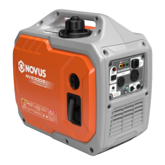
3. Components 3.1 Machine Parts 1. Left bracket of inner liner 2. Fuel tank cap 3. Right bracket of inner liner 4. Panel cover 5. Control panel 6. Fuel valve switch 7. Recoil handle 8. Recoil cover 9. Spark plug cover 10. -
Page 14: Control Panel
3.2 Control Panel (1)Reset button (2)Oil alarm (3)Fault indicator (4)Running indicator (5)USB ports (6)L5-30R (7)Ground wire post (9)Co Alarm (8)5-20R (10)Energy saving switch - 10 -... -
Page 15: Control
4. Control 4.1 3-in1 Switch Knob The switch knob should be placed in "ON" position to warm up the engine before starting the generator. The switch knob should be in "OFF" position to turn off the generator. The switch knob should be placed in "Choke"... -
Page 16: Trouble Sign
overloaded or other failures have caused the controller overheat, engine over-speeding, or the generator is short-circuited. At this time, the controller warns you or stops the generator from working to protect the generator and connected electrical equipment. When the overload indicator (red) is on and the running indicator(green)is off, the engine will not stop. -
Page 17: Running Indicator(Green
2. If the green light is off and the red light flashes once every 2.5 seconds, this indicates overload protection and interrupts the output. 3. If the green light is off and the red light flashes twice at interval of 2.5 seconds, it indicates a short circuit, and the output is interrupted. -
Page 18: Ground Terminal
red light is flashing or remains on, determine the cause of the fault based on the flashing pattern. Press the reset button to restore the generator's output voltage. The issue is considered resolved only when the green light is constantly on without the red light flashing or remaining on. -
Page 19: Co Sensor
The neutral is bonded to the engine. The portable generator inverter and engine are isolated from the AC receptacle ground pin. 4.8 Co Sensor The CO sensor monitors for the accumulation of poisonous carbon monoxide gas around the generator when the engine is running. - Page 20 The YELLOW light will flash for at least five minutes after a fault. When the yellow light turns on, the generator cannot be started and must be repaired immediately. A CO sensor fault can only be diagnosed and repaired by an authorized NOVUS service center.
-
Page 21: Check Before Use
5. Check Before Use Be sure to perform a pre-use check before each use. BEFORE STARTING THE GENERATOR Verify that: • Inspect the generator and any attachments for damage, such as the fuel system, outlets, exhaust system, wiring, and extension cords. •... -
Page 22: Engine Oil Check
Avoid overfilling the tank, as fuel may overflow from the filler port when the tank warms up. Do not exceed the red warning level. Ensure the fuel tank cap is securely tightened. Wipe off any spilled fuel immediately after refueling. Use only unleaded gasoline, as leaded gasoline can cause serious damage to the ... - Page 23 Pay attention to the oil level when adding oil. Recommended oil:SAE 10W -30 Engine oil capacity:0.37 qt. Choose the suitable oil based on annual average temperature of your location. Temperature Engine oil -13℉~86℉ 10W-30 5℉~104℉ 15W-40 Do not run the generator if the amount of oil is insufficient, otherwise generator...
-
Page 24: Operating Instructions
6. Operating Instructions Do not use the generator in a closed space. The exhaust gas from the generator may cause people to lose consciousness or even die in a short time. Please use it in a well-ventilated place. The generator is not filled with oil for transportation; ensure it is sufficiently filled before starting. -
Page 25: Starting
6.1 Starting Do not connect any electrical equipment before starting the generator. Ensure suitable engine oil and gasoline are added. 1. Make sure that the vent switch of the fuel tank cap is set to the “ON” position. 2. Set the knob to the "Choke" position, ready to start. -
Page 26: Shut Down
5.Wait for 50 seconds after successful startup, then plug in the load to supply power. It is normal to need several attempts to start the generator if it hasn't been started for a while or if the gasoline has been depleted. The generator will not start if the control switch is in the shutdown position. - Page 27 6.2.2 Wait 50 seconds 6.2.3 Turn the knob to the “OFF” state 6.2.4 Turn the oil tank knob to the OFF Attention: If you do not plan to use the generator for a long period, please drain the fuel and gasoline line in advance. - 23 -...
-
Page 28: Power Connection
6.3 Power Connection Before inserting the plug (connecting to the terminal), ensure that all electrical equipment is turned off. Before connecting to the generator, ensure that all electrical equipment, including wires and plugs, is in good condition. Confirm that all loads carried by the generator are within the rated load range. ... -
Page 29: Application
7. Application Before using the generator, please confirm that the total load is within the rated load range of the generator, otherwise the generator may be damaged. Each device will display the number of applied power on its nameplate. Multiple DC loads can be used at the same time, but the total power cannot exceed the rated output power. -
Page 30: Maintenance
*1..Change the oil for the first time after one month or after 20 hours of operation;; *2..The air filter should be cleaned more frequently when used in humid or dusty areas; ★…These items should be maintained by NOVUS Company. - 26 -... -
Page 31: Maintenance Chart
8.1 Maintenance Chart Turn off the engine before maintenance! Check before Every 6 12th month or Item Regular check months or 300 hours 100 hours (Everyday) Check status Spark plug ○ ○ Clean or replace if necessary Fuel Check the oil level for leaks ○... -
Page 32: Spark Plug
8.2 Spark Plug The spark plug is an important part of the engine and must be checked regularly. 1. Remove the spark plug cap ①, and place the sleeve ② in the proper position of the spark plug. 2. Insert the screwdriver ③ into the sleeve, turn it counterclockwise, and remove the spark plug. -
Page 33: Carburetor
8.3 Carburetor The carburetor is an important part of the engine. The adjustment should be performed by dealers with professional knowledge and the appropriate equipment to ensure it is done correctly. 8.4 Engine Oil Change Do not drain the oil immediately after turning off the generator. -
Page 34: Air Filter
8.5 Air Filter 1. Remove the air filter cover and foam filter element①. 2. Clean the foam filter element with solvent and dry. 3. Add oil to the foam filter element and squeeze out the excess oil. The foam filter element should be wet, but it should not be dripping with oil. -
Page 35: Spark Arrestor Clean
8.6 Spark Arrestor Clean After the engine has started, the engine and the muffler will become very hot. During inspection and maintenance, please do not allow your skin and clothes to directly touch the engine and the muffler. 1. Remove the muffler grille ①... -
Page 36: How To Store Your Machine
9. How to Store Your Machine Empty Fuel Tank 1. Set the switch knob to the OFF position. 2. Unscrew the fuel tank cap and take out the filter. Extract all the fuel in the fuel tank into an appropriate container for fuel storage, and then tighten the fuel tank cap. 3. -
Page 37: Troubleshooting
10. Troubleshooting Engine won't start 10.1 Fuel system No gasoline in the combustion chamber……………….Check carburetor. No gasoline in the fuel tank…………………………………..Add fuel. There is fuel in the tank……………Confirm that the vent knob of the fuel tank cap is open. Fuel filter is jammed………………………………….Clean the fuel filter. -
Page 38: Specification Sheet
11. Specification Sheet Model NV2300iS Product name Gasoline inverter generator Fuel type Gasoline Power type Rate power/kW Max power/kW Rated voltage/V Rated current/A Gasoline Capacity 1.2 gal. Running time/h 12.5 hours(25% load) Machine Starting Recoil start Sound level/dB(A) Max altitude/m <4000... -
Page 39: Electrical Schematic
12. Electrical Schematic - 35 -... -
Page 40: Parts List
13. Parts List Wearing Parts Material Code Description 1202000018-0001 Cylinder Head Gasket 1900200018-0001 Carburetor 1900200018-0001 Carburetor Gasket 1900100029-0001 Intake Port Gasket 2204700004-0001 Spark Plug 1906100018-0001 Exhaust Port Gasket 1200800079-0001 Cylinder Head Gasket 1903700044-0001 Air Filter Foam Element 1101400033-0001 Crankcase Gasket 360800050 Oil Seal - 36 -... - Page 41 Fuel Tank Components Material Code Description 1800100310-0002 Fuel Tank Assembly 3018200006-0001 Rubber Snap Ring 1814900004-0001 Fuel Tank Rubber Gasket 1802500012-0001 Fuel Tank Shock Absorbing Pad - 37 -...
- Page 42 Panel Components Material Code Description 360410046 Cross Recessed Pan Head Screw 3421600001-0001 Stepped Bolt 2200101673-0001 Control Panel Assembly 2200300018-0003 Control Panel Cover - 38 -...
- Page 43 Left Frame Components Material Code Description 3009600003-0001 Cable Clamp 2617200001-0009 Starter Cover Plate Stepped Bolt 3421600002-0001 (Q235_M6*7_Step Φ10*9) Stepped Bolt 3421600001-0001 (Q235_M5*10_Step Φ6*5) - 39 -...
- Page 44 2454500005-0003 Left Inner Liner Bracket Clip Nut (Q235_M5_Blue 3421400001-0001 White Zinc) Cross Recessed Pan Head 360450036 Self-Tapping Screw - 40 -...
- Page 45 Right Frame Components Material Code Description Non-Standard Cross Recessed 3421700001-0001 Round Head Bolt (m5*20) Engine Oil 2617400001-0009 Maintenance Cover Plate Removable Cover 2617300001-0009 Plate - 41 -...
- Page 46 Shock Absorbing 3400400005-0001 Rubber Pad Stepped Bolt 3421600002-0001 (q235_m6*7_Step φ10*9) 3421400001-0001 Clip Nut Right Inner Liner 2454600005-0003 Bracket Spark Plug Cover 2617500001-0010 Plate - 42 -...
- Page 47 Muffler Outer Cover Components Material Code Description 3411900001-0001 Internal Toothed Lock Washer (Φ5) 3400500003-0001 Rear Cover Gasket 1908100011-0003 Muffler Outer Cover 3421600001-0001 Stepped Bolt (Q235_M5*10_Step Φ6*5) - 43 -...
- Page 48 Oil Switch Components Material Code Description 360410049 Cross Recessed Pan Head Screw 1803500012-0001 Fuel Tank Switch Assembly (Start, Run, Stop) 361310001 Wall Plate Self-tapping Screw 361310002 Wall Plate Self-tapping Screw 1816300095-0001 Fuel Pipe Assembly 1816300097-0001 Fuel Pipe Assembly 1804300014-0001 Fuel Filter Assembly 1816300098-0001 Fluororubber+Chloroether Rubber - 44 -...
- Page 49 Inverter Components Material Code Description Inverter 3100400013-0001 3412400001-0001 Hex Flange Bolt Small Series - 45 -...
- Page 50 Base Plate Components Material Code Description 2434300025-0001 Shock Absorption Support (Neoprene) 360220079 Hex Flange Bolt Small Series 3421400001-0001 Clip Nut (Q235_M5) 3421500001-0001 Non-standard Square Nut 1602900003-0001 Base Plate 360040008 Type 2 Hex Flange Nut (GB/T6177.1_M6) 3400400004-0001 Shock Absorbing Rubber Pad 360220027 Hex Flange Bolt Small Series - 46 -...
-
Page 51: Year Limited Warranty
Novus Performance Products LLC certifies that Novus Products are fit for ordinary purposes for which a product of this type is used. Novus Performance Products LLC however, limits the implied warranties of merchantability and fitness in duration to a period of two (2) years in consumer use, ninety (90) days for any other use. - Page 52 IMPLIED WARRANTIES, SO THE ABOVE LIMITATIONS MAY NOT APPLY TO YOU. Novus Performance Products LLC shall not be liable under any circumstances for any incidental or consequential damages or expenses of any kind, including, but not limited to, cost of equipment rentals, loss of profit, or cost of hiring services to perform tasks normally performed by Novus Products.
Need help?
Do you have a question about the NV2300iS and is the answer not in the manual?
Questions and answers