Table of Contents
Advertisement
Quick Links
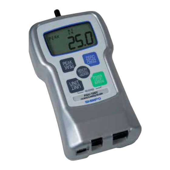
FGV-XY Digital Force Gauge
Operation Manual
Do not operate or store instrument in the following
locations:
Explosive areas, near water, oil, dust or chemicals; ar-
eas where the temperatures can exceed 104°F
(40° C)
Take precaution to not drop the force gauge. Damage
to the sensor may occur.
Do not modify, disassemble or attempt to repair the
unit. Send to the factory for proper repair.
If upon delivery damage to the unit is detected, do not
operate the unit. Notify the shipping carrier immedi-
ately to obtain damage claim instructions.
Only measure forces that are in line with the measur-
ing shaft. Do not attempt to take any measurements
(tension or compression) at any angle. Failure to keep
measurements in line will damage the instrument.
Digital Force Gauges with 180° reversible display & dual labeled
keypad for both push, pull applications. The Series FGV-XY Force
Gauges combine a rugged, ergonomic and compact design to
provide a complete force testing instrument. These instruments
are utilized in a variety of applications such as, incoming quality
inspection, finished goods testing, R&D or almost any portable
or force stand testing requirement.
Onboard statistical calculations provide fast access to maxi-
mum, minimum, average and standard deviation data. The To-
riemon USB software and USB cable allow further data analysis
on a PC. The 1,000 point memory allows for data exporting in
real time or after testing is complete. In addition, the RS-232C
and analog outputs provide the FGV-XY maximum communica-
tion flexibility. Models are available from 0.5 lbs to 200 lb ranges
providing a large offering for various testing requirements. The
180° reversible display combined with the adjustable force direc-
tion and dual labeled keypad enable the FGV-XY to excel in both
compression and tension applications in any direction.
Typical applications include wallboard, wire pull, wire crimps,
trigger pull, brake pedal, aerospace ceramic, springs, food ripe-
ness, corrugated paper strength, blister pack, medical compo-
nent, muscle strength, ergonomic testing, adhesives, syringe
plunger, needle sharpness and many more.
Capacity: 0.5 to 200 lb (200 g to 100 kg)
Accuracy: ±0.2% F.S.
Display: 4-Digit LCD, 0.5" (12 mm) high, Unit 0.29" (7 mm).
Reversible by the push of a button. Minus sign for tension
Display Update: 0.05, 0.1, 0.2, 0.3, 0.5, 1 sec
Sampling Rate: 1000 Hz
Overload: 200% of F.S. (200 lb.: 150% F.S.)
Power: Rechargeable Ni-MH battery or universal AC adapter/
charger (100-240VAC, 50-60Hz)
Output: Analog: ±1 V dc (through a 12 bit D/A converter);
RS232C: Baud rate (19200, 9600, 4800, 2400 bps selectable),
commands control; USB: Allows communication between
FGV-XY and Windows
PC Software with Toriemon USB via
®
USB cable (included); Overload Comparator: Open-collector
output (Max 30 V dc/5 mA)
Auto Power Shut-Off: Yes (not active if adapter/charge is
in use)
Battery Charge: 12 hours (when fully charged)
Recharge Time: Approximately 18 hours (when fully dis-
charged)
Temperature Range: 32 - 104°F (0 - 40°C)
Dimensions: 5.8 x 3 x 1.5" (147 x 75 x 38 mm)
Product Weight: Approx. 1 lb (450 g); FGV-200XY Approx.
1.1 lb (500 g)
Package Weight: Approx. 2.4 lb ( 1.09 kg) for 0.5 lb and 1
lb ranges; 2.6 lb (1.12 kg) for 2 to 100 lb ranges; 2.75 lb (1.25
kg) for 200 lb range
Approvals: CE, RoHS
Warranty: 1 Year
Included Accessories: AC adapter/charger, carrying case,
hook, chisel, flat head, notched head, hanger, cone head,
thread Adapter, extension rod, USB cable.
Advertisement
Table of Contents

Related Manuals for Seals Nidec FGV-XY

Summary of Contents for Seals Nidec FGV-XY
- Page 1 FGV-XY Digital Force Gauge Operation Manual Do not operate or store instrument in the following locations: Explosive areas, near water, oil, dust or chemicals; ar- eas where the temperatures can exceed 104°F (40° C) Take precaution to not drop the force gauge. Damage to the sensor may occur.
- Page 2 Safety Precaution *Retain this manual for future reference It is extremely important for safety that all warnings and cautions are observed exactly per this manual. Warning Serious injury or possibly even death may result if the gauge is used wrongly Caution A serious problem or issue may result if the gauge is used wrongly Safety Precaution Symbols...
- Page 3 Safety Precaution Caution Do not use and keep FGV under the Do not use AC plug covered with dust. following circumstances. •Dusty, salinity and iron content environments •Location which will be gotten water A potential fire hazard may exist •Location which will be gotten oil and chemical •Locations which receive direct sunlight •Dew condensation place •Corrosive and Flammable gas environment...
-
Page 4: Table Of Contents
INDEX 1. Product Features 6.7. Recalling memory data 2. Included Accessories 6.7.1. Continuous memory mode 3. Product Diagram 6.7.1.1. Measuring memory data 3.1. Main unit 6.7.1.2. Statistics memory data 3.2. Display Outline 6.7.2. Single memory mode 3.2.1. Numeric display 6.7.2.1. Measuring memory data 3.2.2. -
Page 5: Product Features
1.Product Features • Nickel-hydrogen battery for long time use: 4.1. Charge • Data can be downloaded to PC with USB: 6.9. USB communication • 1000 data point memory: 6.6. Memory • Comparator shows pass or fail. ( I/O output of the result): 6.5. Comparator •... -
Page 6: Product Diagram
3. Product Diagram 3.1.Main Unit Sensor shaft Apply your force in line with this threaded shaft. Use the included attachments for your testing application Display LCD screen is unit's main information display PEAK key Press PEAK to change measuring modes UNIT key Press UNIT to switch to available measurement units ZERO key... -
Page 7: Display Outline
3.2.Display Outline unit comparator judgement MAX/MIN measuring value peak hold mode 3.2.1.Numeric Display Display the measuring value with sign and 4 digits numbers. Compression force: plus, Tension force: minus. (It's available to switch plus/minus with the setting of function (f01)). Reverse display is available. -
Page 8: Before Use
4.Before use 4.1.Charge Only charge with Please use AC adaptor supplied with the FGV. An alternate adaptor supplied AC adaptor. could cause damage and fire. 1. Please connect the attached AC adapter into the AC adapter of the body, and then plug the adaptor into an outlet port •... -
Page 9: Tracking
4.4.Tracking A load cell strain gauge is used for the FGV force sensing. This type of sensor can alter its output due to changes in temperature. The tracking feature algorithm can negate this slight change. When measuring very small forces, an error could arise while tracking is on. -
Page 10: Function Setting
5. Function setting The following setting items in function mode. Item Unit Set contents Default factory setting Display sign -0001(minus), 0001 (plus) 0001 Display update time 1, 2, 3, 5, 10, 20 (times/second) Auto power off 10 (10 minutes), oFF (not valid) RS-232C baud rate 2400, 4800, 9600, 19200 (bps) 2400... -
Page 11: Display Update Time: F02
5.2.Display update time: f02 It's available to set the display update time for 1 time/second, 2 times/second, 3 times/second, 5 times/second, 10 times/second and 20 times/second. After the setting, the averaging value within display update time is shown every display update time. Press the UNIT key to choose the display update time (1, 2, 3, 5, 10, 20 (times/second), Press the PEAK key to move ahead. -
Page 12: Response Time: F05
5.5.Response Time : f05 The response time function smooths out the gauge's sampling, and adjustis the sampling period accordingly The available response times are 3, 20, and 150 msec. Press UNIT to change the setting, PEAK to save and move to the next function, or ZERO to save and finish. Key operation Display Response time 3msec Response time 20msec Response time 150msec... -
Page 13: Feature And Operation
6.Feature and Operation 6.1.Overview of operation 1. Basic operation Operation POWER Turn the POWER ON/OFF ZERO Tare (Peak reset at the PEAK Hold mode) PEAK Standard measuring mode / Plus peak hold mode / Minus peak hold mode UNIT Change the unit Store the measuring data into memory 2. -
Page 14: Measuring Mode
6.2.Measuring Mode Standard measuring mode or peak hold modes are available. 6.2.1Standard measuring mode It's available to measure the compression and tension force. Measuring value appears at all times. 1. Press POWER key and release ( Turn POWER on after release) 2. -
Page 15: Comparator
6.5.Comparator 6.5.1.Comparator Compare HI / LO limits which you entered. The results appear on the display. In addition, an output signal of the result is available with the data output port. In order to activate the comparator function, set Hi-Lo at External output (f06) in the function settings. When you set "ovEr"... -
Page 16: Setting Lo Limit
6.5.4.Setting LO limit 1. Press PEAK key during comparator HI limit setting, then move to LO limit setting. 2. Setting way is the same as the comparator HI limit setting. 3. Press MEM key, then setting value is registered, and move to standard measuring mode. 4. - Page 17 [Definisions of the terms] Measuring value: Displayed value which is per display update time at standard measuring mode. Plus maximum value (+MAX): Maximum value at plus side which is measured within memory measuring interval. Minus maximum value (-MAX): Maximum value at minus side which is measured within memory measuring interval. Plus minimum value (+MIN): Minimum value at plus side which is measured within memory measuring interval.
-
Page 18: Setting Memory Mode
6.6.1.Setting memory mode Turn the POWER off. Press PEAK key and hold, then press POWER key. Comparator HI limit setting turns on, then press PEAK key twice. Memory setting mode turns on. There are following setting items for comparator • memory setting mode. Item Display Content... -
Page 19: Storing Data
6.6.2.Storing data Store the data at setting memory mode (single memory, continuous memory, standard memory). 6.6.2.1.Continuous memory mode 1. During the standard measuring mode, press MEM key. “M” will blink, unit starts to record. Press MEM key, measurement wil cease, then display of the unit is changed from M into the unit. -
Page 20: Recalling Memory Data
6.7.Recalling memory data 6.7.1.Continuous memory mode 6.7.1.1.Measuring memory data 1. Turn the POWER off. Press MEM key and hold, then press and release POWER. Release MEM when you see "CNT" on the display. The unit will alternate between showing the data block number, and the recorded measurement value of that block. 2. -
Page 21: Statistics Memory Data
6.7.1.2.Statistics memory data 1. When in memory mode, UNIT will cycle through the available statistics data. 2. Each press of UNIT will switch between the following items: positive maximum value, negative maximum value, positive minimum value, negative minimum value, positive peak value, average value, standard deviation. 3. -
Page 22: Single Memory Mode
6.7.2.Single memory mode 6.7.2.1.Measuring memory data 1. Turn POWER off. Press MEM key and hold, then press and release POWER. Release MEM when you see "Slg" on the display. The unit will alternate between showing the data block number and the recorded measurement value of that block. 2. -
Page 23: Statistics Memory Data
6.7.2.2.Statistics memory data 1. When in memory mode, UNIT will cycle through the available statisics data. 2. Each press of UNIT will switch between the following items: positive maximum value, negative maximum value, positive minimum value, negative minimum value, average value, standard deviation. 3. -
Page 24: Standard Memory Mode
6.7.3.Standard memory mode 6.7.3.1.Measuring memory data 1. Turn the Power off. Press MEM and hold, then press and release POWER. Release MEM when you see "STd" on the display. The unit will alternate between showing the data block number, and the recorded measurement value of that block. 2. -
Page 25: Statistics Memory Data
6.7.3.2.Statistics memory data 1. When in memory mode, UNIT will cycle through the available statistics data. 2. Each press of UNIT will switch between the following items: positive maximum value, negative maximum value, positive minimum value, negative minimum value, positive peak value, and negative peak value. 3. -
Page 26: Erasing All Memory Data
6.8.2.Erasing all memory data (1)When last memory data is displayed, all data will be erased if you press ZERO key for at least 5 seconds. (2)Display switches to standard measuring mode after showing “nonE” for one second at measuring display. (3)All memory data of current memory mode is erased. -
Page 27: External Connection
7.External Connection 7.1.Pin assignment Signal Name HR12 - 10RC - 10SDL made in Hirose is Number used for connector. Analog + Analog GND R x D (RS-232C Received data) Host computer; FGP Digital GND Detection of Connection T x D (RS-232C Transmitted data) FGP;... -
Page 28: Rs-232C Communication Command
7.2.2.RS-232C communication command •Typical communication command "cr"means carriage return. Transmitting command Returning command from host Content Explanation from FGV computer to AAcr Tare AAcr ABcr Cancel of data transmission ABcr ACcr Switch to plus peak hold mode ACcr ADcr Switch to standard measuring mode ADcr ALcr Switch to minus peak hold mode... -
Page 29: Connection Between Fgv And Pc
7.2.3.Connection between FGV and PC Host computer (Connector for data output port) (D - SUB 9 pin) R x D Please be sure to connect 5pin into 4 pin of digital GND when Digital GND making cable for RS-232C on your own. It cannot be transmitted Detection of without this connection. -
Page 30: Frequently-Asked Questions
8.Frequently – asked questions 8.1.Troubleshooting Questions Cause Presumable reason Procedure When turning on power, “OVR” is It is possible that internal Unit was dropped or Contact a dealer for repair displayed even if not applying loadcell is broken. overloaded. load and cannot be cleared by pushing ZERO key. -
Page 31: Dimensions
10.Dimensions Force Gauge Adapter with M4 Connections: Models FGV-0.5XY & FGV-1XY ~ Flat Head Hook DIMENSION TOLERANCE APPROVED UNITS PARTS NAME ±0.1 Toshi Hook attachment OVER 6 TO ±0.2 CHECKED MATERIAL OVER 30 TO ±0.3 NOTE 2 OVER 120 TO ±0.5 OVER 400 TO... - Page 32 Force Gauge Adapter with M6 Connections: Models FGV-2XY through FGV-200XY Note: Hook to 100 lb only. 100 lb. Hook Flat Head DIMENSION TOLERANCE APPROVED UNITS PARTS NAME Toshi DIMENSION TOLERANCE APPROVED UNITS PARTS NAME ±0.1 Flat attachment Toshi ±0.1 OVER 6 TO ±0.2 Hook attachment...
Need help?
Do you have a question about the Nidec FGV-XY and is the answer not in the manual?
Questions and answers