Advertisement
FG-7000TA Digital Torque Gauge
Operation Manual
Operators should wear protection such as a mask and gloves in case
pieces or components break away from the unit under test.
Whether the unit is ON or OFF, DO NOT exceed the capacity of the
sensor. NEVER exceed 120% of the rated capacity, or the torque sensor
will be damaged. At 110% of the rated capacity the display will flash
a warning.
If mounting FG-7000T Series Digital Torque Gauges, use M4 mounting
screws with a maximum insertion depth of 7 mm into the gauge. Hand
tightens mounting screws, DO NOT use tools. Do not use damaged
clamp.
Measure in line torque only. DO NOT attempt to measure forces at an
angle to the sensor – damage to sensor may result.
Do not attempt to repair or alter this instrument. Warranty will be voided
and damage to the unit may result.
Use and store within the stated temperature and humidity ranges, or
damage and failure may result.
If not using this instrument for extended periods of time, remove the
batteries to prevent potential battery leakage from causing product
damage.
DO NOT use tools to over torque the connection adapter. Hand-tighten
only so damage does not occur.
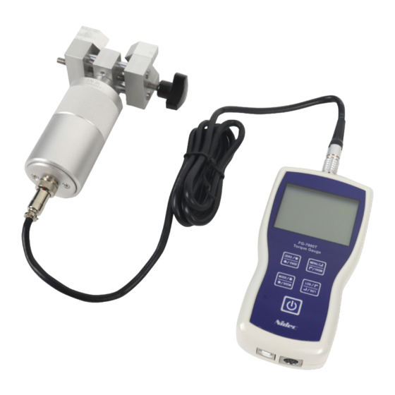
The FG-7000TA Series digital torque gauges provide testing flex-
ibility with their external torque sensor input. Torque sensors with
the adustable clamp adapter are immediately recognized when
connected to the display base. Units are available for your specific
testing needs in 1 N-m (9 in-lb) 5 N-m (44 in-lb) & 10 N-m (88 in-lb)
capacities. The adjustable clamping mechanism enables flexible
test size operation from approximately 0.56 to 2" (14 to 50 mm)
diameters. Four selectable modes of operation include: Track
mode for live readings, Peak mode for displaying the maximum
reading, First Peak where only the initial peak is recorded once a
decrease is sensed and Preset which initiates user-programmed
tolerance alarms for go/no go testing. The display has two se-
lectable operations, numerical view with directional bar graph or
graphical view with directional bar graph. In graphical view when
alarm tolerances are set, the process is plotted in relation to the
upper and lower limit graph lines. Combined with the go/no go
icons, a simple pass/fail determination is recognized. These high-
tech instruments can data log a reading at the push of a button
for simple data acquisition or be set to continuous data storage.
Data can be viewed on the screen, sent to the optional printer, or
loaded to be analyzed and graphed on the free software program.
The 1,000 point memory with definable groups allows for multiple
tests to be recorded and easily separated upon loading. In addi-
tion, the comparator output can be set up for integration of the
instrument into a quality system for repetitive testing such as on
a production line. The large back-lit, 180° auto-reversible display,
CW/CCW directional bar graph, combined with the dual labeled
key pad allows for usage of the gauge in various positions while
still being able to easily view and operate. These various features
make the FG-7000T the ideal torque instrument for various appli-
cations such as closing or opening analysis of containers, valves
and door hardware, failure or destructive torque testing, or almost
any torque testing requirement involving incoming quality inspec-
tion, finished goods testing to R&D.
SEALS USA, Inc.
Instruments Division
SPECIFICATIONS
Accuracy: ± 0.3% F.S.
Selectable Units: N-m, N-cm, kgf-cm, lbf-in (Depending on
Range)
Overload Capacity: 120% of F.S. (LCD flashes beyond 110% of
F.S.)
Measurement method: Peak, First Peak Preset or Track Mode
Data Sampling Rate: 1000 Hz
Display: 160*128 dot matrix LCD with LED Backlight
Display Update Rate: 10 times/second
Resolution: (See page 2 Resolution Table)
Memory: 1000 data
Set Point: Programmable high and low limits
Battery Indicator: Display flashes battery icon when battery is
low
Power: 3.6VDC 800mAH Ni-MH rechargeable batteries
Battery Life: Approximately 16 hours continuous use per full
charge
Charger / Adapter: Universal USB/BM charger, Input: 110 ~
240VAC
Temperature Effects: <0.054% per °F (0.03% FS per °C)
Outputs: USB, Serial Port RS-232, High & Low Limit NPN
Operating Temperature: 14 to 104°F (-10 to 40°C)
Storage Temperature: -4 to 122°F (-20 to 50°C)
Oper. Relative Humidity: 5 to 95%
Storage Relative Humidity: 20 to 80%
Housing: Aluminum
Dimensions: 5.7 x 2.9 x 1.4" (145 x 73 x 35.5 mm)
Product Weight: 3.5 (1.6 kg)
Package Weight: 5.3 (2.4 kg)
Warranty: 1 year
Certification: CE
Included Accessories: AC Adapter/Charger, USB cable, carry-
ing case, calibration cert.
Tel: (630)924-7138
Adjustment Clamp
Email: support@seals-usa.com
Advertisement
Table of Contents

Related Manuals for Seals Nidec FG-7000TA

Summary of Contents for Seals Nidec FG-7000TA
- Page 1 Included Accessories: AC Adapter/Charger, USB cable, carry- any torque testing requirement involving incoming quality inspec- ing case, calibration cert. tion, finished goods testing to R&D. SEALS USA, Inc. Adjustment Clamp Instruments Division Tel: (630)924-7138 Email: support@seals-usa.com...
-
Page 2: Resolution Table
1. LCD SCREEN STANDARD VIEW Test Mode Icons: Track: Real Time, live measuring mode Peak: Reading will not change until a higher value is mea- sured Preset: Set the upper & lower limit for GO/NG testing First Peak: Captures First Peak after a decrease has been detected. -
Page 3: Key Functions
3. KEY FUNCTIONS From the home screen, touch “MENU” to enter the main menu. (Figure 4-1) All keys are capacitive touch. ON/OFF: Push for 2 seconds to power On or Off During Measurement: Print the current force value or store data, depending on the key setting. (See 4.5.8 for key setting) In Menus: Back or quit. - Page 4 4.2.4 Test Mode Load a standard force on the gauge. Wait a moment for the Change the mode of operation between the four modes. force to stabilize. The current value (2) should equal the stan- Press “ZERO” or “MODE” keys to select. Press “LOG” to can- dard force applied.
- Page 5 4.3.2 Browse All The data will be displayed. Touch “ZERO” or “MODE” keys to shift to the next position. Touch “MENU” to see Delete or Print options. Touch “LOG” to go back. (Fig. 4-3c) Figure 4-4b Figure 4-4c 4.4.1 Print Recent Print recently stored data in this menu.
- Page 6 4.5.1 Display Mode 4.5.6 Date/Time Two display modes may be selected: Digital and Graphic (Fig- The system time may be set under this menu. Touch “ZERO” ure 4-5c). If diagram is chosen, select the diagram’s scale. to adjust the value. Press “MODE” to shift to the next position. (Figure 4-5d) Touch “LOG”...
- Page 7 4.6 Language Select between English, German and Chinese (Figure 4-6a) Figure 6-1a Figure 4-6a 6.2.1 RS232 4.8 Information The RS232 serial port is used to connect a printer to print the memory data. Information includes the model, version of the software and the serial number.
- Page 8 160*128 Dots LCD Adapter (See LCD Screen) Connection Robust Metal Housing Capacitive Touch Keys USB Port: Recharge the internal Communications Port Ni-MH battery or (See Figure 6-1a) connect to PC 7.3 Dimensions SEALS USA, Inc. Instruments Division Tel: (630)924-7138 Email: support@seals-usa.com...
Need help?
Do you have a question about the Nidec FG-7000TA and is the answer not in the manual?
Questions and answers