Table of Contents
Advertisement
Quick Links
Advertisement
Table of Contents

Related Manuals for Designs for Vision REVEAL FC


Summary of Contents for Designs for Vision REVEAL FC
- Page 1 ® ® UIDE Model: REVEAL ® Ver. 3-24...
- Page 2 . REVEAL ® ESIGNS FOR ISION The Designs for Vision REVEAL ® FC system combines bright, portable light with evaluation glasses creating a lightweight fluorescent guided system. NDICATIONS FOR The Designs for Vision REVEAL ® FC is an illumination device used to aid in autofluorescent visualization.
- Page 3 Always examine the unit and accessories for damage before commencing use. Damaged accessories must not be used and must be replaced. Use original Designs for Vision, Inc. parts and accessories only. The use of unapproved parts may void the warranty.
- Page 4 This equipment and accessories do not contain serviceable parts. All repairs need to be conducted by Designs for Vision, Inc. service personnel Do not let liquids enter openings or ports. Do not immerse parts in solutions. Allowing liquids to enter openings or ports may void warranty.
- Page 5 Remove battery from power pack if this device is not in use and will be stored for some time. Maintain storage at environmental conditions listed below Improper use of battery may cause them to get hot, ignite or explode. Always follow all safety precautions listed in this manual Never make changes or modifications to the battery pack...
- Page 6 Do not use within 8 inches of electrocautery devices to maintain proper function Always use a cloth to clean/disinfect products Any serious incident that has occurred in relation to the device should be reported to the manufacturer and the competent authority of the Member State in which the user and/or patient is established.
- Page 7 Do not remove or tamper with marking and/or ID numbers on your device. Will void the warranty. Do not force the protective case closed. Re- position loupes if necessary. May cause damage if placed in case improperly. Do not remove rubber protective insert from case EVEAL FC UIDE...
- Page 8 ±10% UltraMini REVEAL ® mW/cm ±10% RUNTIME Measured with a fully charged battery High 10 hours +/-10% UltraMini ReVeal FC: ® 19 hours +/-10% DIMENSIONS POWER PACK: 3.60” x 1.95” x .95” WEIGHT: 4.9 oz. REVEAL 1.33” x .770” ®...
- Page 9 TRANSPORT & STORAGE TEMPERATURE: C to 70 RELATIVE HUMIDITY: 10% to 100% including condensation ATMOSPHERIC PRESSURE: 500 to 1060 hPa ENVIRONMENTAL OPERATING CONDITIONS TEMPERATURE: C to 40 RELATIVE HUMIDITY: 30% to 75% ATMOSPHERIC PRESSURE: 700 to 1060 hPa APPROVALS IEC 60601-1, IEC 60601-1-2, Class A, CISPR 11, IEC 62133, IEC 62366-1 EQUIPMENT CLASS: Class II INGRESS OF WATER:...
-
Page 10: Table Of Contents
ONTENTS Device Description .............. 11 Using Your Loupes_____________________________ ..12 How to start: ..............12 Attaching the Retaining Straps ........13 LED DayLite ® ™ Initial Setup and charging ....14 Holster Operation ............17 Understanding the Status Indicator ....... 19 Replacing the Battery ............. -
Page 11: Device Description
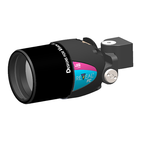
EVICE ESCRIPTION The REVEAL FC generates a 3” spot at a 16” working ® distance. This light provides illumination autofluorescence guided applications and should be used with the REVEAL observational glasses ® The Reveal ® FC includes these main components: Power Pack LEDSC Desktop Charger w/Power Cord REVEAL... -
Page 12: Using Your Loupes
_____________________________ SING OUPES OW TO START Your Reveal Observational Glasses are designed with special emission filters that work together with the excitation light produced by the headlight. The observation glasses block out all the excitation light while transmitting all other wavelengths. -
Page 13: Attaching The Retaining Straps
Your observational glasses have the T-mount pre-installed on the frame. Figure 2 TTACHING THE ETAINING TRAPS Your Reveal ® Observational Glasses come with retaining straps to help them remain comfortably in place during procedures. The straps are slid over the ends of the temples (Fig. -
Page 14: Hdi
LED D ® ™ NITIAL ETUP AND CHARGING Remove the components from the shipping container, checking that all parts on the packing NOTE: The list have been received. Carefully batteries need to remove the headlight, power pack(s), receive a full charge before desktop charger and charger cord... - Page 15 Plug the cord into the jack connector on the front of the power pack (Fig. 5). Plug the power cord into the charger and connect the desktop charger to the AC outlet. NOTE: International cords are available through Designs for Vision; refer to the list on page 25. EVEAL FC UIDE...
- Page 16 The power button light will start pulsing to indicate the unit is in “Smart Charge” mode. The status indicator (Fig. 6) will display the current state of charge. The LED will change colors as the battery charges; going from ORANGE to GREEN.
-
Page 17: Holster Operation
OLSTER PERATION In addition to the holsters, Ratcheting Belt Clips have been included to allow for a full 360° rotation of the unit, even while it is attached to you. To place the belt clip on to the holster, simply slide it up over the raised circular ratchet disk until an audible ‘click’... - Page 18 Each increment is followed by an audible click. To remove the power pack from the clip, depress the button on the top of the belt clip while pulling up on the power pack, which is shown by arrow B (Fig. 9). NOTE: Make sure power pack is properly seated before commencing use.
-
Page 19: Understanding The Status Indicator
NDERSTANDING THE TATUS NDICATOR The LED DayLite® HDi ™ incorporates an advanced status monitoring system. The following table describes what each indication signifies: OLID REEN ULLY HARGED ATTERY OLID ULSING ATTERY LINK ENERAL RROR LEASE CONTACT ESIGNS FOR ISION FOR FURTHER ASSISTANCE LINK ATTERY... -
Page 20: Replacing The Battery
The LED DayLite® HDi™ also incorporates a Low Battery Warning system. With approximately ten (10) minutes of battery power remaining, the headlight will flash three times. At five (5) minutes remaining, the headlight will flash another three times. At 30 (thirty) seconds remaining, the headlight will flash continually until the battery is completely depleted. -
Page 21: Using The Reveal ® Fc Headlight
Unplug the black connector on the battery on the inside of the unit. Note: Replace with Designs for Vision, Inc. battery only. Using unapproved batteries may not work and will void the warranty. Insert the new battery being very careful to install in the proper orientation. -
Page 22: Connecting Your Headlight
can then be locked into that position using the provided driver (if equipped). Locate the hex in the locking shaft of the headlight (Fig. 11). Place the driver into this opening and turn clockwise to tighten the shaft. To unlock the position, loosen the shaft by turning counter-clockwise. - Page 23 port on the top or side of the power pack. Clips and a cable wrap are also supplied to be used in conjunction with your frame to direct the cable away from your face. The power pack MUST BE OFF when plugging any light into the pack.
-
Page 24: Using The Mobile Device Clip-On Filter
SING THE MART EVICE ILTER To capture images of auto fluorescence with the Reveal FC, slide the clip-on filter over your camera on any mobile device. Press inwards on the top of the clip then slide the clip down until it covers the camera’s lenses on the... -
Page 25: Replacement Parts
INDICATES CONFORMITY WITH MDR EU 2017/745 INDICATES WHERE THE UNIT CAN BE TURNED ON AND OFF INDICATES BATTERY STATE OF CHARGE INDICATES WHERE THE UNIT CAN BE CHARGED READ ACCOMPANYING DOCUMENTS WASTE ELECTRICAL AND ELECTRONIC EQUIPMENT (WEEE) DIRECTIVE SYMBOL EPLACEMENT ARTS ESCRIPTION UMBER... -
Page 26: Electromagnetic Information
Reorient or relocate the receiving device Increase the separation between the equipment Consult Designs for Vision, Inc. for help Table 201 – Guidance and Manufacturer’s Declaration – Emissions All Equipment and Systems Guidance and Manufacturer’s Declaration – Emissions... - Page 27 ® The LED DayLite is intended for use in the electromagnetic ™ environment specified below. The customer or user of the LED DayLite should ensure that it is used in such an environment. ™ Electromagnetic Environment- Emissions Test Compliance Guidance ®...
- Page 28 Electromagnetic Immunity IEC 60601 Compliance Environment – Test Test Level Level Guidance ±8kV Contact ±8kV Contact Floor should be wood, concrete IEC 61000-4-2 ±2kV, ±4kV, ±15kV Air or ceramic tile. If ±8kV, ±15kV floors are synthetic, the r/h should be at least 30%.
- Page 29 1 Cycle and 1 Cycle and requires continued 70% U : for 70% U : for operation during 25/30 Cycles 25/30 Cycles power mains interruptions, it is Single Phase: Single Phase: recommended at 0˚ at 0˚ that the LED ® DayLite ™...
- Page 30 Electromagnetic Immunity IEC 60601 Compliance Environment - Test Test Level Level Guidance Conducted Disturbances 0.15 MHz- 0.15 MHz to induced by RF 80 MHz 80 MHz Fields 6 V in ISM 6 V in ISM IEC 61000-4-6 bands bands between between Interference may 0.15MHz...
- Page 31 Table 206 – Recommended Separation Distances between portable and mobile RF Communications equipment and the LED DayLite® HDi™ Equipment and Systems that are NOT Life-Supporting Recommended Separations Distances for the LED DayLite ® ™ The LED DayLite is intended for use in the electromagnetic ®...
- Page 32 GSM 1800; 1720 CDMA 1900; Pulse 1700 - GSM 1900; 1845 Modulation 1990 DECT; LTE 217 Hz Band 1, 3, 4, 1970 25; UMTS Bluetooth, WLAN, Pulse 2400 - 802.11 2450 Modulation 2570 b/g/n, RFID 217 Hz 2450, LTE Band 7 5240 Pulse 5100 -...
- Page 33 LED DayLite ® ™ , including cables specified by Designs for Vision, Inc. Otherwise, degradation of the performance of this equipment could result. The EMISSIONS characteristics of this equipment make it suitable for use in industrial areas and hospitals (CISPR 11 class A).
-
Page 34: Inspection And Preventative Maintenance
mitigation measures, such as relocating or re-orienting the equipment. The LED DayLite ® ™ may be adversely affected by EM DISTURBANCES possibly resulting in a loss of light output. The LED DayLite is intended to be used during HF ® ™... - Page 35 Internal batteries must be replaced every 24 months to • ensure proper operation • Your Designs for Vision, Inc product utilizes precision Anti-Reflective coatings. Clean lenses with a standard glass cleaner and a soft, lint-free cloth, making sure not to scratch the surface.
- Page 36 • Not intended to be sterilized. Do not autoclave. It is recommended for disinfection that all exposed plastic sections be wiped with Clorox Verasure surface disinfectant/cleaner or an equivalent plastic-safe cleaner. Do not use alcohol, phenol, ammonia, or iodine complex solutions. If a cleaner that contains alcohol must be used, make sure it contains no more than 20% alcohol.
-
Page 37: Warranty
Any damage caused by improper maintenance as described in the manual may not be covered by the warranty Designs for Vision, Inc (the “Company” warrants its Surgical Loupes as to material, manufacturing and workmanship, to the original purchaser for the life of his or her practice. - Page 38 If your eyeglass prescription changes and you want it • updated into your loupes, contact Designs for Vision Customer Service Department and request a quote. Contact our Customer Service Department before you •...
- Page 39 Pack in a box with packing list and copy of invoice • Ship to: Designs for Vision, Inc. • 4000 Veterans Memorial Hwy. Bohemia, NY 11716-1024 Attn: Repairs EVEAL FC UIDE...
- Page 40 MADE IN AMERICA ECHNICAL SUPPORT USTOMER ERVICE 1.800.345.4009 Outside the US-Call Local Distributor Manufactured by Designs for Vision, Inc Emergo Europe BV 4000 Veterans Memorial Hwy Bohemia, NY 11716 Prinsessegracht 20 2514 AP, United States The Hague NETHERLANDS EVEAL FC UIDE Toll Free 800/345-4009 •...
Need help?
Do you have a question about the REVEAL FC and is the answer not in the manual?
Questions and answers