
Subscribe to Our Youtube Channel
Related Manuals for Pilot Communications BARISTA ATTITUDE 2GR

Summary of Contents for Pilot Communications BARISTA ATTITUDE 2GR
- Page 1 ESPRESSO COFFEE MACHINE Use and Maintenance Manual. TECHNICIAN’S Instructions. ORIGINAL INSTRUCTIONS...
- Page 2 IMPORTANT: Read carefully before use. Store for future reference All rights reserved on contents The total or partial reproduction and the dissemination of this document’s contents is forbid- den without the Manufacturer’s prior written authorisation. The Company logo is owned by the Manufacturer of the Machine.
- Page 3 SAFETY PRECAUTIONS the following paragraphs as they cannot be eliminated. I.I. LEVEL OF TRAINING AND Compliance with the installation and ma- chine’s safety standards is dependent on the KNOWLEDGE REQUIRED OF use, installation, maintenance and correct op- THE TECHNICIAN eration of the machine. These factors are the responsibility of the purchaser, Technician and The Technician is a specialised person that has Technician’s employer.
- Page 4 INSTALLATION I.IV. is not powered, the Technician must apply the rules prescribed by current technical standards Electrical hazard (disconnect the power supply, avoid re-closures, check that there is no voltage, etc.). High temperature hazard MAINTENANCE AND CLEANING I.V. Risk of explosion Electrical hazard It is prohibited to perform mainte- nance on moving components...
- Page 5 When cleaning, pay attention to the parts of EMERGENCY SITUATIONS I.VI. the machine that can become hot: Should an emergency situation occur as a result • Avoid contact with the dispensing group, of a machine malfunction, adopt the measures water spouts and steam nozzles. provided for in the emergency plan posted in •...
-
Page 6: Table Of Contents
General contents INTRODUCTION ..............7 Washes ..................41 Guidelines for reading the Manual ........7 View the dispensing cycle ...........42 Storing the Manual ..............7 Coffee temperatures .............43 Method for updating the Instruction Manual ....7 Language ...................43 Recipients ..................7 Recipe library ................43 8.10 Water filters ................45 Glossary and Pictograms ............8 Guarantee ..................9 8.11 Parameter list ................46... -
Page 7: Introduction
1. INTRODUCTION 1.2 Storing the Manual The Instruction Manual must be stored carefully. The manual Read this manual carefully. It provides important safety infor- should be stored, handled with care with clean hands and not mation to the Technician regarding the operations indicated placed on dirty surfaces. -
Page 8: Glossary And Pictograms
RECIPIENT QUALIFICATIONS Personal protective equipment (PPE) The machine is intended for a professional non-generalised Clothing or equipment worn by someone to protect their use, therefore the Technician must: health or safety. • Have attended the training courses organised by the Intended use Manufacturer relating to the type of machine. -
Page 9: Guarantee
1.6 Guarantee ATTENTION symbol used when there is a risk of minor injury that could require medical attention. All of the machine's components are covered by a 12-month guarantee, except for electrical and electronic components and parts prone to wear and tear. WARNING symbol used when there is a risk of mi- If any work is carried out on the machine electronics when nor injury that could be treated with first-aid or... -
Page 10: Intended Use
2.4 Intended use General safety features The Technician must be aware of accident risks, safety devices The espresso coffee machine has been designed to profes- and the general safety rules set forth in EU directives and by sionally prepare hot beverages such as tea, cappuccinos and the legislation of the country where the machine is installed. -
Page 11: Machine Diagram
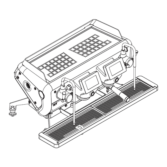
2.5 Machine diagram Start-up light switch. Steam lever. Anti-scalding steam nozzle. Hot water nozzle. Logo back light. Adjustable foot. Filter holders. Dispensing compartment LED light. Display touchscreen. 10. Cup holder grille. 11. Cup warmer surface. 12. Manual coffee button. 13. USB SOCKET (*) 14. -
Page 12: Control Panel
2.6 Control panel The machine is completely controlled via the touchscreen display located on the front. In case of problems, the display will also show machine malfunctions, if any: Beverage selection buttons Control access Machine alarms START/STOP button Beverage selection buttons EXIT button Cup warmer MONDAY... -
Page 13: Internal Components
2.7 Internal components Cup warmer heating element Water filling solenoid valve Heating unit heating element Double non-return valve Dispenser SCNR valve (expansion + non-return) Hot water mix solenoid valve Air suction pump Motor pump 10. Discharge conveyor 11. Volumetric dosing device 12. -
Page 14: Data And Marking
2.8 Data and marking The machine’s general technical data is provided in the fol- lowing table: MODEL 220-240 V Power 3.300 - 4.650 W 4.600 - 6.700 W 380-415 V Frequency 50 - 60 Hz 50 - 60 Hz Heating unit capacity 14.7 l Width 1022 mm... - Page 15 Energy Saving System Dispensing group 2.8.1 2.8.3 The machine is equipped with software that manages the The system anticipates the heating of the dispensing group automatic standby system during breaks, the night energy- (1) through a thermosiphon circuit (2) connected to the heat saving feature and the smart temperature adjustment.
- Page 16 Electronic control unit Overflow device 2.8.4 2.8.8 The electronic control unit is the machine’s The cover installed on the pressure “brain”, since it monitors and controls the ap- relief valve makes it possible to col- pliance’s full operation. lect any water and steam which may The information concerning the installed soft- leak from the heating unit due to a ware (date and version) can be seen on the...
- Page 17 2.8.14 Expansion valve + non-return valve 2.8.17 Cup warmer This is a valve consisting of an expansion valve and a check valve. Place the cups to be heated on the specific shelf (11). • Expansion valve (A): the cold water sent by the pump to the exchanger is heat- ed.
- Page 18 2.8.19 Water softener 2.8.20 Automatic steam wand (optional) The resin water softener can be used as an alternative to the This system can be used for automatically heating and froth- Water Filter. ing milk at the programmed temperature. This component has the property of retaining the calcium con- The operating principle is listed below: tained in the water.
-
Page 19: Transport And Handling
3. TRANSPORT AND HANDLING 3.5 Unpacking the machine Only remove the machine from its packaging when it is ready to 3.1 Safety precautions be installed, in order to prevent accidental collisions which could damage it: Carefully read the instructions provided in the •... -
Page 20: Lifting The Machine
3.6 Lifting the machine The machine can only be lifted by a solid grip of its legs or feet. Do not move the machine by its other components (steam nozzles, filter holders, drain tray, etc.) as this could lead to the components becoming damaged and/or breaking, and potentially cause the ma- chine to fall. -
Page 21: Installation
5. INSTALLATION 5.4 Installation and operation spaces Before the machine arrives, a suitable environment must be 5.1 Safety precautions prepared: Carefully read the instructions provided in the • The appliance is not suitable for installation in an area chapter I. where a water jet may be used. - Page 22 Support base Grinder-dispenser 50 cm minimum distance between the machine and the wall Sewer drain Discharge conveyor Height of the upper part of the machine from the floor min 150 cm Adjustable feet of the machine Electrical mains switch Water filter inlet 10.
-
Page 23: Drilling Of The Support Bench
5.6 Drilling of the support bench If holes need to be drilled into the support base to let the wa- ter inlet hoses, outlet hoses and power cables pass through, follow the directions given in the drawings below. 2 GROUPS SCARICO DRAIN Ø100mm... -
Page 24: Hydraulic Connection
5.7 Hydraulic connection Hydraulic connections 5.7.3 The Technician must carry out the hydraulic connections in Before connecting the hydraulic system, make sure accordance with the hygiene and hydraulic safety standards that the appliance has been disconnected from the regarding environmental protection which are in force in the electrical mains. - Page 25 Water mains and drain connection Electrical connection 5.7.4 5.7.5 • Place the machine in the position foreseen by the drilling • The conformity of the electrical system, effectiveness of pattern of the support bench the earthing system and functionality of the differential circuit breaker - all of which are fundamental for guaran- •...
-
Page 26: Commissioning
6. COMMISSIONING 6.3 Turning the machine on and off During the machine's heating-up phase, the nega- 6.1 Safety precautions tive pressure valve and the water nozzle will release steam for a few seconds until the valve closes. Carefully read the instructions provided in chapter Every day the water in the machine must be re- placed. -
Page 27: Internal Water Replacement
Heating in progress... Please wait it is sufficient to wait for a few seconds to allow the tempera- At the end of the start-up, the thermal regulation phase be- ture to fully adjust: the display will return to its normal bright- gins. -
Page 28: Energy Saving
6.5 Energy Saving Two “Energy Saving” types of system can be activated: To turn off the machine or activate the Energy Saving mode, MANUAL proceed as follows: The Energy Saving functions can only be activated manually by selecting the Stand-by and Shutdown icon. -
Page 29: Automatic Steam Wand
7. MACHINE INFORMATION 6.6 Automatic steam wand The machine information is available on the display: 6.6.1 Adjusting the temperature • Select the button. To programme the temperature of the milk to be heated, see para. • Select the menu button 8.4. -
Page 30: Parameter Programming
8. PARAMETER PROGRAMMING Access via the USB Key 8.1.1 • Remove the side panel. This paragraph shows all of the programming menus where the various machine functions can be set. • Insert the specific USB key into the reader (11). All these operations are carried out via the touchscreen display. -
Page 31: Programming Menu
Access with Password 8.2 Programming menu 8.1.2 • Select the button. You can access the machine’s full programming mode from the two menu pages. • Select the menu button The following is a summary diagram of the programming sec- • Select the service settings button tions, the parameters involved and the operations envisaged. -
Page 32: Maintenance
8.3 Maintenance date of last wash view enabling the automatic enable Inspections 8.3.1 wash In this section, you can monitor all of the machine’s operating wash at each start-up enable data in real time, such as: number of wash cycles set (no.) •... - Page 33 Counter list 8.3.2 All of the counts for the dispensed doses are available in this sec- tion, such as: • the partial No. of single coffees dispensed since the last reset shown as: short, normal and long for each group •...
- Page 34 User button activation 8.3.3 In this section, the technician can enable or disable the items in the user menu. With value 1, the button is enabled, with a value of 0, the button is deactivated. The “Enable Shortcut Parameters button” item makes the icon available.
- Page 35 Maintenance thresholds 8.3.4 This section is dedicated to managing the machine’s maintenance: • A-B-C maintenance threshold; • Viewing the remaining cycles until the A-B-C threshold; • Viewing the next date for the A-B-C maintenance threshold; SERVICE SETTINGS • Days remaining until maintenance; Service Maintenance Washes...
- Page 36 Maintenance report 8.3.5 The following information can be viewed in this section: • Type A maintenance cycles; • Type B maintenance cycles; • Type C maintenance cycles; SERVICE SETTINGS • Date of next maintenance; Service Maintenance Washes parameters Coffee View delivery Language •...
- Page 37 Alarm history Heating units efficiency 8.3.6 8.3.7 This section can be consulted to check all of the anomalies that In this section it is possible to check the efficiency of the services have occurred on the machine over time. heating unit. The comparison of the various parameters over time makes it possible to evaluate the operating status of the heating unit: Press the "test”...
- Page 38 Restoring the parameters Heating unit inspection 8.3.8 8.3.9 In this section, you can restore the initial programming data. In this section it is possible to test the operation of the safety valve of the heating unit. The heating element is powered and thus the pressure of the To activate the restore procedure, select the desired button heating unit increases until the safety valve opens.
- Page 39 8.3.10 Actuator test This section can be used to test all the machine’s main components. By pressing the respective button, the machine will activate the cor- responding component, thus allowing you to check that it is working ACTUATOR TEST properly. Group 1 SV To go from one page to another, select the button.
-
Page 40: Service Parameters
8.4 Service parameters The parameters regarding machine services can be set up in this section, such as: • heating unit pressure; • temperature of the heating unit in energy saving mode; • milk temperature short dose; SERVICE SETTINGS • milk temperature medium dose; Service Maintenance Washes... -
Page 41: Washes
8.5 Washes In this section you can programme the automatic wash cycles and the management of the washes: • See the date of the last wash; • Enable the automatic wash; • Enable the automatic wash at each start-up; SERVICE SETTINGS Service Maintenance Washes... -
Page 42: View The Dispensing Cycle
8.6 View the dispensing cycle In this section of the programming mode, you can enable which information is displayed while doses are being dispensed: • the time; • the flow rate; • the temperature. SERVICE SETTINGS Use the buttons to enable or disable the function. Service Maintenance Washes... -
Page 43: Coffee Temperatures
8.7 Coffee temperatures 8.9 Recipe library This function is not available. In this section, coffee recipes can be created and customised, as follows: • recipe name; • group temperature. 8.8 Language This will allow the user to recall the desired blend at In this section, the language used on the machine's display can any time without having to be set. - Page 44 8.9.1 Programming doses on the standard model Copy one dose to another 8.9.2 To copy a scheduled dose to another, proceed as follows: • Press the button to start dispensing. Start • Press the copy button ( ) on the dose selection screen. •...
-
Page 45: Water Filters
8.10 Water filters Do not remove the filter holder from the dispens- ing group when coffee is being dispensed. This section is dedicated to water softener and filter manage- ment. With this system, you can: Each dose must be programmed with ground cof- •... -
Page 46: Parameter List
8.11 Parameter list All the machine’s parameters can be programmed in this section. Use the buttons or the display keyboard edit the information. To go from one page to another, select the button. 2/11 The complete list of all parameters is provided in chap. -
Page 47: Energy Saving & Cloud
8.12 Energy saving & cloud Through this section, it is possible to modify the stand-by param- eters of the machine, and adjust working days and hours. • Select the type of savings you want: • select day • using buttons , or the display keyboard set the desired time by confirming with the OK button SERVICE SETTINGS... -
Page 48: Software
8.13 Software Use the USB key to update the machine’s software and upload useful information, in particular: • CPU, TFT and language update; • Advanced update; • Upload slides; SERVICE SETTINGS • Import parameters; Service Maintenance Washes parameters Coffee • Save parameters; View delivery Language temperatures... -
Page 49: Wi-Fi Connection
9. WI-FI CONNECTION INFO If WIFI service is set up on the machine (optional), it is pos- sible to connect as follows: Keypad software version Ver. 338 Rev. 013.13 01/04/2016 • Check if the wording , which appears on the lower- Basic software version Ver. -
Page 50: Maintenance And Cleaning
10. MAINTENANCE AND CLEANING 10.3 Maintenance 10.3.1 Scheduled maintenance 10.1 Safety precautions Perform the following maintenance activities according to Carefully read the instructions provided in the the specified frequency. chapter I. If the machine is used intensively, the checks need to be per- formed more frequently. - Page 51 Component Type of operation 3 months 1 Year 2 Years Check that the safety valve is operating correctly as indicated in para.10.3.5 Should it become necessary to replace it, as a result of malfunctions, repeat SAFETY VALVE the check of the new valve installed. Replace the safety valve every 2 years.
- Page 52 10.3.2 Maintenance after a short period 10.3.5 SAFETY VALVE check of machine inactivity The pressure relief valve is one of the main components for machine safety. Therefore, it is important to carry out the fol- "Short period of machine inactivity" refers to a period of time lowing checks: exceeding one working week.
-
Page 53: Water Filter Maintenance
10.3.7 CHECK DRAIN -NON-RETURN 10.4.2 Bypass configuration VALVE Depending on the hardness of the water, adjust the bypass of the water filter as shown in the table below. Example: The non-return drain valve is an important component for the correct operation of the machine. Perform the check as follows: •... - Page 54 10.4.3 Technical data Model Connection 3/8" 3/8" 3/8" 3/8" coupling type Min.- max. water sup- ply pressure (bar) Water temperature 4-30 4-30 4-30 4-30 min. - max. (°C) Room temperature 4-40 4-40 4-40 4-40 min-max (°C) Total height (A) without bracket (mm) Total height (B) with bracket (mm) Connection (C)
-
Page 55: Water Softener Regeneration
10.5 Water softener regeneration In order to keep the water softener, and hence the machine, in perfect operating condition, it is necessary to regularly re- It is very important to regenerate the softener within the es- generate it, depending on the softener and hardness of the tablished times. -
Page 56: Malfunctions And Relative Solutions
10.7 Malfunctions and relative solutions Problem Cause Action The main switch is in the OFF position. Turn the main switch to the ON position. NO POWER TO THE The machine switch is faulty. Replace the main switch. MACHINE The mains switch is in the OFF position. Turn the mains switch to the ON position. - Page 57 Problem Cause Action The filter holder is dirty. Clean the filter holder. The filter holes are worn. Replace the filter. GROUNDS FOUND IN CUPS The coffee has not been ground evenly. Replace the burrs. The group gasket is worn. Replace the seal. The pump pressure is too high.
-
Page 58: Cleaning Operations
10.8 Cleaning operations 10.8.2 Cleaning the filters and filter holders Caution: only immerse the filter holder cup in wa- 10.8.1 General instructions ter and try not to get the handle wet. A few simple cleaning tasks are required to have a perfectly Daily: sanitised and efficient appliance. - Page 59 10.8.5 Arbitrary dispensing group wash Use the EVO ® detergent according to the proce- dures indicated on the packaging or on the manu- facturer's website. If desired, it is possible to wash the groups at any time, pro- ceeding as follows: •...
-
Page 60: Spare Parts
10.8.6 Cleaning the unit spray heads, 10.8.7 Cleaning the steam nozzle For the weekly cleaning of the steam nozzle, use the spray head holder and filter holder MFC ® detergent diluted in water according to the pro- Daily cedures indicated on the packaging or on the manufac- turer's website. -
Page 61: Display Warnings
12. DISPLAY WARNINGS Code Warning Cause Action Check how many groups have been set in the A001 INFO: Initial self-test Negative initialisation cycle. machine. Switch the machine off and back on again.. A002 INFO: date not set Date and time are missing. Set the Date and Time. - Page 62 Code Warning Cause Action INFO: Timeout communication A020 between base card and expansion Communication error board - pumps Switch the machine off and back on again. pumps INFO: PWM expansion pump A021 PWM expansion pump overcurrent Switch the machine off and back on again. overcurrent WARNING: Overpressure steam A022...
- Page 63 Code Warning Cause Action WARNING: Overpressure coffee The pressure of the coffee heating unit is too A050 Check the heating unit and the hydraulic circuit. group heating unit high. Check group solenoid valve. A051 WARNING: Group solenoid valve Defective or disconnected group solenoid valve. If necessary replace the solenoid valve.
-
Page 64: Decommissioning
13. DECOMMISSIONING 15. DISPOSAL For the European Union and the European Economic Area only. 13.1 Short period of machine inactivity "Short period of machine inactivity" refers to a period of time exceeding one working week. If the machine is reactivated after this period, the Technician must replace all the water contained in the hydraulic circuits as indicated in para. -
Page 65: Electrical Diagrams
16. ELECTRICAL DIAGRAMS 16.1 Connection to the POWER SUPPLY GNYE (*) Per il Brasile CAVO A 3 CONDUTTORI (Fase+Neutro+Terra) Phase GNYE Phase Phase Neutral Earth Blue Power supply cable Grey CAVO A 4 CONDUTTORI (3 Fasi+Terra) GNYE Yellow-green Brown Black GNYE CAVO A 5 CONDUTTORI (3 Fasi+Neutro+Terra) -
Page 66: Single-Phase High Voltage Electrical Diagram
16.2 Single-phase high voltage electrical diagram A.11 A.22 A.12 A.21 ALIM L1L1 A.13 A.20 ALIM Power supply Power supply cable Power supply filter Main switch SIGLA DESCRIZIONE Power supply terminal board Voltage change terminal board ALIM Alimentatore Cavo alimentazione Motor pump Interruttore generale Morsettiera Alimentazione Steam heating unit heating element... -
Page 67: Ul Single-Phase High Voltage Electrical Diagram
16.3 UL single-phase high voltage electrical diagram A.11 A.22 A.12 A.21 ALIM L1L1 A.13 A.20 F1=15A F2=15A ALIM Power supply Power supply cable Fuse 6.3 A Main switch Power supply terminal board SIGLA DESCRIZIONE Voltage change terminal board ALIM Alimentatore Motor pump Cavo alimentazione Fusibile... -
Page 68: Three-Phase Star High Voltage Electrical Diagram
16.4 Three-phase star high voltage electrical diagram A.11 A.22 A.12 A.21 ALIM A.13 A.20 T R S ALIM Power supply Power supply cable Power supply filter Main switch Power supply terminal board Voltage change terminal board SIGLA DESCRIZIONE Motor pump ALIM Alimentatore Steam heating unit heating element... -
Page 69: Three-Phase Triangle High Voltage Electrical Diagr
16.5 Three-phase triangle high voltage electrical diagram A.11 A.22 A.12 A.21 ALIM A.13 A.20 -MAL ALIM Power supply T R S Power supply cable Power supply filter Main switch Power supply terminal board Voltage change terminal board SIGLA DESCRIZIONE Motor pump Steam heating unit heating element ALIM Alimentatore... -
Page 70: Low Voltage Electrical Diagram 2Gr
16.6 Low voltage electrical diagram 2GR ALIM Power supply Connector Volumetric dosing device Automatic steam wand solenoid valve Heating unit charging solenoid valve Group solenoid valve Mixed water solenoid valve Proportional solenoid valve Tea solenoid valve Fuse LED.F Front LED LED.R Rear LED Motor pump... -
Page 71: Low Voltage Electrical Diagram 3Gr
16.7 Low voltage electrical diagram 3GR ALIM Power supply Connector Volumetric dosing device Automatic steam wand solenoid valve Heating unit charging solenoid valve Group solenoid valve Mixed water solenoid valve Proportional solenoid valve Tea solenoid valve Fuse LED.F Front LED LED.F2 LED.R Rear LED... -
Page 72: Change Power Supply
16.8 Change power supply 7. Loosening the screws (A), remove the rear panel of All the operations to change the power supply volt- the body (B); age of the machine must be carried out exclusively by a Technician specifically qualified and autho- rised by the Manufacturer. - Page 73 7. Remove the washer and the nut and earthing cable(H). Make sure not to low the screw fall behind, we recommend keeping it tight and immediately replacing the washer and nut in position; 8. Remove the power supply cable (L); 9.
- Page 74 ELECTRICAL DIAGRAMS COUPLINGS THREE-PHASE STAR TYPE COUPLING THREE-PHASE TRIANGLE TYPE COUPLING SINGLE-PHASE COUPLING (with neutral) (without neutral) POWER SUPPLY CABLE POWER SUPPLY CABLE POWER SUPPLY CABLE TERMINAL BOARD TERMINAL BOARD TERMINAL BOARD CONNECTORS CONNECTORS CONNECTORS INSTRUCTIONS TO CHANGE POWER SUPPLY FROM THREE-PHASE STAR SHAPED - TO SINGLE-PHASE Kit for the coupling of single-phase: •...
- Page 75 Attention: avoid creating curves that are too tight on the cables 12. Install the new earthing cable (Q) by fastening it with the washer and nut; 13. Lock the cable with the cable gland (G); 14. Replace the cable gland (E) on the protection; TECHNICIAN’S manual...
- Page 76 15. Install the cover (D) fastening with the screws (C); 16. Replace the rear panel on the body (B) locking it with the screws (A); 17. Loosen the screws (S) and remove the lower panel of the left side (R); 18.
- Page 77 21. Change the position of the terminal board connectors (Y) as indicated in the Electrical Diagrams provided on page 74; 22. Fasten the cover (Z) of the electrical box with the screws (V); 23. Replace the electrical box (U) pushing it inside the machine; 24.
- Page 78 26. Connect the machine to the mains; 27. Turn on the machine and heat it for at least 1 hour; 28. Turn off the machine and disconnect it from the mains again; 29. By acting on the screws (A), remove the rear body panel (B); 30.
-
Page 79: Hydraulic Diagram
17. HYDRAULIC DIAGRAM Steam valve Water filling solenoid valve Nozzle hot water outlet Dispensing group Heating unit pressure transducer Group solenoid valve Negative pressure valve Volumetric dosing device Hot water solenoid valve Motor pump Safety valve Pump pressure adjustment Non-return valve Water inlet filter Solenoid valve to regulate hot water mix Water inlet connection... -
Page 80: Parameters Table
18. PARAMETERS TABLE DESCRIPTION PARA. MINIMUM SETPOINT TEMPERATURE 60 - 110°C DESCRIPTION GR3 HEATING UNIT DISPENSING PARA. GR3 HEATING UNIT TEMPERATURE TEMPERATURE 0 = °C SETPOINT IN STANDBY MEASUREMENT UNIT 1 = °F MAXIMUM FLOW VARIATION NUMBER OF GROUPS 1 - 4 5 - 100 PERCENTAGE 0 = Disabled... - Page 81 DESCRIPTION PARA. ENABLING THE BUTTON: 0 = Disabled “Counter list” 1 = Enabled 0 = Disabled 187 ENABLING THE “FILTERS” BUTTON 1 = Enabled ENABLING THE BUTTON: 0 = Disabled “Set services shortcut” 1 = Enabled 0 = Energy saving 189 THE MACHINE’S IDLE MODE 1 = OFF 0 = single...
- Page 84 CMA MACCHINE PER CAFFÈ S.R.L. Via Condotti Bardini, 1 - 31058 SUSEGANA (TV) - ITALY Tel. +39.0438.6615 - Fax +39.0438.60657 www.barista-attitude.com - info@barista-attitude.com Cod. 02000968 - Rev. 01 - 05/2024...
Need help?
Do you have a question about the BARISTA ATTITUDE 2GR and is the answer not in the manual?
Questions and answers