Table of Contents
Advertisement
Quick Links
Service Overview
D500TD_Service_manual
COPYRIGHT INFORMATION
No part of this manual, including the products and software described in it, may be reproduced,
transmitted, transcribed, stored in a retrieval system, or translated into any language in any form or by any
means, except documentation kept by the purchaser for backup purposes, without the express written
permission of ASUSTeK COMPUTER INC.("ASUS").
ASUS PROVIDES THIS MANUAL "AS IS"WITHOUT WARRANTY OF ANY KIND, EITHER
EXPRESS OR IMPLIED, INCLUDING BUT NOT LIMITED TO THE IMPLIED WARRANTIES
OR CONDITIONS OF MERCHANTABILITY OR FITNESS FOR A PARTICULAR PURPOSE.
IN NO EVENT SHALL ASUS, ITS DIRECTORS, OFFICERS, EMPLOYEES OR AGENTS BE
LIABLE FOR ANY INDIRECT, SPECIAL, INCIDENTAL, OR CONSEQUENTIAL DAMAGES
(INCLUDING DAMAGES FOR LOSS OF PROFITS, LOSS OF BUSINESS, LOSS OF USE OR
DATA, INTERRUPTION OF BUSINESS AND THE LIKE), EVEN IF ASUS HAS BEEN
ADVISED OF THE POSSIBILITY OF SUCH DAMAGES ARISING FROM ANY DEFECT OR
ERROR INTHIS MANUAL OR PRODUCT.
Products and corporate names appearing in this manual may or may not be registered trademarks or
copyrights of their respective companies, and are used only for identification or explanation and to the
owners' benefit, without intent to infringe.
SPECIFICATIONS AND INFORMATION CONTAINED IN THIS MANUAL ARE
FURNISHED FOR INFORMATIONAL USE ONLY, AND ARE SUBJECTTO CHANGE AT
ANY TIME WITHOUT NOTICE, AND SHOULD NOT BE CONSTRUED AS A
COMMITMENT BY ASUS. ASUS ASSUMES NO RESPONSIBILITY OR LIABILITY FOR ANY
ERRORS OR INACCURACIES THAT MAY APPEAR IN THIS MANUAL, INCLUDING THE
PRODUCTS AND SOFTWARE DESCRIBED IN IT.
Copyright ○
2023 ASUSTeK COMPUTER INC. All Rights Reserved.
c
LIMITATION OF LIABILITY
Circumstances may arise where because of a default on ASUS' part or other liability, you are entitled to
recover damages from ASUS. In each such instance, regardless of the basis on which you are entitled to
claim damages from ASUS, ASUS is liable for no more than damages for bodily injury (including death)
and damage to real property and tangible personal property; or any other actual and direct damages resulted
from omission or failure of performing legal duties under this Warranty Statement, up to the listed contract
price of each product.
ASUS will only be responsible for or indemnify you for loss, damages or claims based in contract, tort or
infringement under this Warranty Statement.
1-1
V1.0
Advertisement
Table of Contents

Related Manuals for Asus D500TD


Summary of Contents for Asus D500TD
- Page 1 Warranty Statement, up to the listed contract price of each product. ASUS will only be responsible for or indemnify you for loss, damages or claims based in contract, tort or infringement under this Warranty Statement.
- Page 2 Service Overview This limit also applies to ASUS' suppliers and its reseller. It is the maximum for which ASUS, its suppliers, and your reseller are collectively responsible. UNDER NO CIRCUMSTANCES IS ASUS LIABLE FOR ANY OF THE FOLLOWING: (1) THIRD-PARTY CLAIMS AGAINSTYOU FOR DAMAGES; (2) LOSS OF, OR DAMAGE TO,YOUR RECORDS OR DATA;...
-
Page 3: Service Overview
Desktop and necessary cautions and tools before performing any service and repairs. o provide the best service and support for the ASUS DESKTOP D500TD we have provided the below information for technicians from distributors and resellers to perform the complete Desktop disassembly and assembly. -
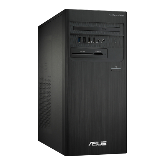
Page 4: Desk Top Pc
Disassembly Procedure DESK TOP PC Overview The illustrations below show the Desktop PC’s overview from front view, side view and back view. Most of the parts will be discussed in this manual. FRONT & BACK VIEW Refer to the following diagram to identify the components on front & back of the system. 2 - 4 V1.0... - Page 5 Disassembly Procedure Components The illustrations below show the components FRONT BEZEL Hard Disk Drive According to shipments on location 2 - 5 V1.0...
- Page 6 Disassembly Procedure According to shipments on location 2 - 6 V1.0...
- Page 7 Disassembly Procedure Mother Board MB RUBBER Memory According to shipments on location Power Supply According to shipments on location VGA CARD According to shipments on location 2 - 7 V1.0...
- Page 8 Disassembly Procedure WLAN Module According to shipments on location CHA FAN ODD Tray base POWER SWITCH HOLDER 2 - 8 V1.0...
- Page 9 Disassembly Procedure According to shipments on location ODD CABLE HDD CABLE SLIM ODD SATA CBL 15P/6P L200 SW HDD LED CABLE CARD READER 2 - 9 V1.0...
-
Page 10: Disassembly And Assembly
Be sure to use proper tools described before. SUS Desktop PC D500TD consists of various modules. This chapter describes the procedures for the complete Desk Top PC disassembly and assembly (Assemble process please look up from the last page). In addition, in between procedures, the detailed disassembly procedure of individual modules will be provided for your service needs. - Page 11 Disassembly Procedure Appropriate Tools The illustrations below show the appropriate tools that should be used for the Desktop service and repair. Automatic Screwdriver Plastic Blade Antistatic Gloves 2 - 11 V1.0...
-
Page 12: Power Off
Disassembly Procedure POWER OFF The illustrations below show how to remove the power cable from the Desk Top PC. Remove the power cord by pulling it from the arrow side. 2 - 12 V1.0... - Page 13 Disassembly Procedure 2 - 13 V1.0...
-
Page 14: Side Cover
Disassembly Procedure SIDE COVER The illustrations below show how to remove the side cover from the Device. 1. Loosen 4 screws of red circle, if you will latch it, please following the step back. DOOR SCREW 2. Pulling out the left and right side CHASSIS cover. Parts ⚫... - Page 15 Disassembly Procedure VGA CARD (Optional) The illustrations below show how to remove the VGA Card from the Device 1. Remove 1 screw on the cover. 2. Open the screw cover. 3. Remove 1 screw as below. 2 - 15 V1.0...
- Page 16 Disassembly Procedure SCREW #6-32 L6*H2.3 (B) Parts ⚫ VGA CARD*1 ⚫ Total screws *2 2 - 16 V1.0...
- Page 17 Disassembly Procedure WLAN CARD (Optional) The illustrations below show how to remove the WLAN CARD from the Device 1. Disconnect the antenna cable on WLAN card , unscrew the screw and remove the WLAN card. SCREW M2*3L 2 - 17 V1.0...
- Page 18 Disassembly Procedure 3. Remove 1 screw inside and take out the BRACKET. 4.Remove the WIFI antenna. Parts WIFI CARD*1 ⚫ Total screws *2 ⚫ 2 - 18 V1.0...
- Page 19 Disassembly Procedure The illustrations below show how to remove the SSD from the Desk Top PC 1.Remove 2 screws on the SSD and take out it. SCREW M2*3L 2.Remove the PAD on the MB. Assembly Notice: Add New SSD Sink If the PC has a graphics card, you cannot install Sink.
-
Page 20: Power Supply
Disassembly Procedure Parts SSD*1 ⚫ ⚫ PAD*1 Total screws *1 ⚫ POWER SUPPLY The illustrations below show how to remove the power supply from the Device. 1.Disconnect CPU Power Supply cables (4 PIN and 24PIN). 2.Disconnect HDD & ODD power supply. 2 - 20 V1.0... - Page 21 Disassembly Procedure 3.Remove 4 screws from the PSU and take out it. SCREW #6-32 L6*H2.3 (B) Parts ⚫ PSU*1 ⚫ Total screws *4 2 - 21 V1.0...
- Page 22 Disassembly Procedure ODD&HDD The illustrations below show how to remove the ODD&HDD from the Device 1. Disconnect ODD & HDD SATA cord. 2 - 22 V1.0...
- Page 23 Disassembly Procedure ODD CABLE HDD CABLE SLIM ODD SATA CBL 15P/6P L200 2.Remove 4 screws on the ODD Tray . SCREW M3*4.4L (K) B-ZN #2 3. Remove the ODD. 2 - 23 V1.0...
- Page 24 Disassembly Procedure Push 4. Remove 3 screws on the SLIM ODD BKT. SCREW M3*4.4L (K) B-ZN #2 SCREW M2*2L (K) B-NI NY #1 5.Remove the ODD from Tray base . 2 - 24 V1.0...
- Page 25 Disassembly Procedure 6.Remove 4 screws on the HDD. 2 - 25 V1.0...
- Page 26 Disassembly Procedure Parts SATA3 HDD*1 ⚫ HDD TRAY *1 ⚫ HDD SATA CABLE*1 ⚫ ODD *1 ⚫ ODD TRAY*1 ⚫ ⚫ SLIM ODD SATA CBL 15P/6P L200*1 ODD SATA CABLE*1 ⚫ Total screw *7 ⚫ CPU COOLER & CPU The illustrations below show how to remove the CPU from the Device. 1.Release the cable route of CPU fan.
- Page 27 Disassembly Procedure 2. Rotate the 4 snaps in the direction of the arrow and lift them vertically. 2 - 27 V1.0...
- Page 28 Disassembly Procedure 3 .Pull the fixed foot out of the slot and take off the thermal. 4.Pull out the CPU pole and Lift the other end of the CPU bar about 100o and take CPU away. Lift the other end of the CPU bar about 100o and take CPU away. 2 - 28 V1.0...
- Page 29 Disassembly Procedure ‘ *Pin facing down on Processor Packaging* *Please note that if you wish to install directional, CUP triangle must be aligned MB triangle * 2 - 29 V1.0...
- Page 30 Disassembly Procedure CPU installation notice Parts ⚫ CPU COOLER*1 ⚫ CPU *1 2 - 30 V1.0...
-
Page 31: Memory Module
Disassembly Procedure Memory Module The illustrations below show how to remove the memory from the Desk Top PC. 1 .Press the button in the direction of the arrow. 2. Hold both sides of the memory module with both hands and pull it out vertically. Parts ⚫... -
Page 32: Main Board
Disassembly Procedure MAIN BOARD The illustrations below show how to remove the MB from the Device 1. Release the cables on the MB. Card reader USB2.0 PORT POWER SW Audio CHA FAN USB 3.0 2. Remove 8 screws from MB and take MB away. 2 - 32 V1.0... - Page 33 Disassembly Procedure D500TD MAIN BD Same with red circle screws SCREW M3*4L (W) W-NI SCREW #6-32 L6*H2.3 (B) MB RUBBER Parts ⚫ Total screw *8 ⚫ MAIN BD*1 2 - 33 V1.0...
- Page 34 Disassembly Procedure Power switch & IO Bezel The illustrations below show how to remove the Power switch & IO from the Device 1. Release the IO bezel. 2.Remove the SW HDD LED CABLE. Remove the cable form LED HOLDER (PRESS the lamp). 2 - 34 V1.0...
-
Page 35: Front I/O Board
Disassembly Procedure IO BEZEL SW HDD LED CABLE POWER SWITCH HOLDER (The holder must not be fissured) Parts ⚫ IO BEZEL*1 ⚫ SW HDD LED CABLE*1 ⚫ POWER SWITCH HOLDER*1 FRONT I/O BOARD The illustrations below show how to remove the Front I/O board from the Device 1. - Page 36 Disassembly Procedure SCREW #6-32 L6*H2.3 (B) 2.Remove Front I/O board from device. 3.Remove 2 screws on the FIO CABLE BRKT. SCREW #6-32 L6*H2.3 (B) 4.Take out the FIO from the bracket. 2 - 36 V1.0...
-
Page 37: Audio Module
Disassembly Procedure Notice: FIO EMI GASKET ,AUDIO AL FOIL & USB AL FOIL must not be missed!!! Parts FIO *1 ⚫ Total screws *4 ⚫ Audio Module 1.Remove 2 srews and take out the audio module. 2 - 37 V1.0... - Page 38 Disassembly Procedure 2.Unplug the cables. 2 - 38 V1.0...
- Page 39 Disassembly Procedure 2 - 39 V1.0...
- Page 40 Disassembly Procedure CHA FAN The illustrations below show how to disconnect all of the CHA FAN from the Device 1.Remove 4 screws of fan from the device. SCREW M5*10L (F) W-NI (TP5) Parts ⚫ Total screw*4 ⚫ CHA FAN*1 2 - 40 V1.0...
-
Page 41: Card Reader
Disassembly Procedure CARD READER The illustrations below show how to remove the Card Reader from the Device. 1. Remove 4 screws from device. SCREW M3*4L (W) W-NI 2. Remove Card Reader from device. Parts CARD reader*1 ⚫ Total screws *4 ⚫... - Page 42 Disassembly Procedure APPENDIX If it is necessary to replace CPU or CPU fan when repairing, here is the SOP to daub with CPU grease. 1. Clean old CPU grease by using tissue paper dipped with 70 to 99% alcohol completely. 2.
Need help?
Do you have a question about the D500TD and is the answer not in the manual?
Questions and answers