Table of Contents
Advertisement
Quick Links
Advertisement
Table of Contents

Related Manuals for bemco BEPACP230V05

Summary of Contents for bemco BEPACP230V05
- Page 1 INSTALLATION & USER MANUAL POOL HEAT PUMP INVERTER...
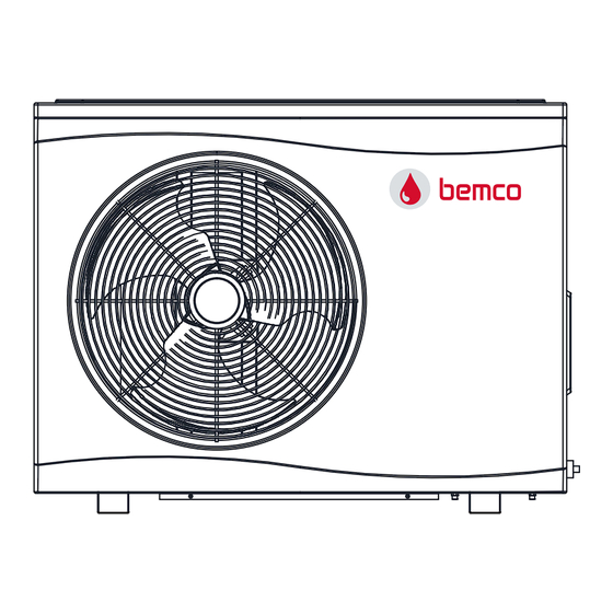
- Page 2 THANK YOU Dear Customer, Thank you for choosing our products and greatly we appreciate your confidence in us! Wave-Inverter These are the Swimming Pool Heat Pumps for heating or cooling your pool and extending your swimming season. This is a special Pool heat pumps which is most close to users and why? It is a smart heat pump who knows how to heat your pool most efficiently and maintain pool temperature, thanks to the full inverter technology.
-
Page 3: Table Of Contents
TABLE OF CONTENT INTRODUCTION ..............................2 This manual ..............................2 The unit ..............................2 SAFETY INSTRUCTIONS ............................3 ITEMS INSIDE PRODUCT BOX ..........................5 OVERVIEW OF THE UNIT ............................ 6 Unit Dimension ............................6 Explode View ..............................7 INSTALLATION ..............................8 Installation information ..........................8 Condition of installation .......................... -
Page 4: Introduction
INTRODUCTION This manual This manual includes the necessary information about the unit. Please read this manual carefully before you use and maintain the unit. The unit The swimming pool heat pump is one of the most economical systems to heat the swimming pool efficiently. -
Page 5: Safety Instructions
SAFETY INSTRUCTIONS To prevent injury to the user, other people, or property damage, the following instructions must be followed. Incorrect operation due to ignoring of instructions may cause harm or damage. Install the unit only when it complies with local regulations, by‐laws and standards. Check the main voltage and frequency. - Page 6 If there is no suitable, earthed wall socket available, have one installed by a recognized electrician. Do not move/repair the unit yourself. Before proceeding with any maintenance, service or repair work, the product must be isolated from the mains electrical supply. Only qualified personnel should carry out these tasks. Improper movement or repair on the unit could lead to water leakage, electrical shock, injury or fire.
-
Page 7: Items Inside Product Box
ITEMS INSIDE PRODUCT BOX Before starting the installation, please make sure that all parts are found inside the box. The Unit Box Item Image Quantity Wave‐Inverter Swimming pool heat pump Installation and Operation Manual Extension cable 15m Cable Water Connectors (55mm) Winter Cover Rubber foots for... -
Page 8: Overview Of The Unit
OVERVIEW OF THE UNIT Unit Dimension MODEL BEPACP230V05/07/09 BEPACP230V11/14/17 BEPACP230V21/23/25 BEPACP230V29/32,BEPACP400V29/32 1076 1176... -
Page 9: Explode View
Explode View Name Name Top Cover Bottom Panel component Electric box cover Inverter compressor Support frame High‐pressure valve Electronic control components Low‐pressure switch Fin heat exchanger Power waterproof cover Left panel Needle valve Motor bracket Controller DC fan motor Four‐way valve Middle panel Water flow switch Right panel... -
Page 10: Installation
INSTALLATION Installation information The following information given here is not an instruction, but simply meant to give the user a better understanding of the installation. Condition of installation The following information given here is not an instruction, but simply meant to give the user a better understanding of the installation. - Page 11 in water flows, more or less important depending on the moisture content, which will gradually diminish. To channel condensation flows, we recommend that you install our condensate drain kit. For this purpose the heat pump must be raised by at least 10 cm. How to install the condensate drain kit? 1.
-
Page 12: Electrical Connection
Electrical supply must correspond to that indicated on the appliance. Connection cables have to be sized according to appliance power and installation requirements. Please refer to below table: Cable size Heat pump BEPACP230V05 3x1.5mm /AWG 16 BEPACP230V07 3x2.5mm /AWG 14 BEPACP230V09 3x2.5mm... -
Page 13: Trial Running
These data are only indication, you must ask an electrician to determine the exact data for your pool installation. Use the cable glands and grommets provided inside the heat pump to routecables. If the length of your cable is more than 10 meters, we advise you to seek advice from a professional. A voltage variation of ±... -
Page 14: Operating The Unit
OPERATING THE UNIT Operating the unit comes down to operating the digital controller. NEVER LET THE DIGITAL CONTROLLER GET WET. THIS MAY CAUSE AN ELECTRIC SHOCK OR FIRE. NEVER PRESS THE BUTTONS OF THE DIGITAL CONTROLLER WITH A HARD, POINTED OBJECT. THIS MAY DAMAGE THE DIGITAL CONTROLLER. -
Page 15: Display Instruction
Display Instruction Instruction for Buttons Start on/off: Short press to turn. Also user can press this button to exit when they finish setting or checking; Run Modes: Short press to switch Heating/Cooling/Auto mode. Long‐Press to into menu option; Increase: Temperature set + or previous one; Decrease: Temperature set ‐... -
Page 16: Instruction For Function
Instruction for Function Switch Modes When the heat pump is on, press briefly to switch between heating/cooling/automatic operation. Each mode has three operation modes: Boost/Smart/Silent. Set Temperature When the heat pump is on, short press to enter the water temperature setting interface, and the water inlet area temperature value flashes. -
Page 17: Function Diagnosis
Display on each status: Parameter Query ParameterSetting Debugging Status Error Query Note: Value twinkles, means it is available for changing, or in verse Function Diagnosis When the heat pump is powered off, dial code 4 to switch to 1, and automatically enter the function detection state after powering on again. -
Page 18: Parameter Checking And Adustment
PARAMETER CHECKING AND ADUSTMENT Parameter list Some parameters can be checked and adjusted by the controller. Below is the parameterlist. Name Instruction Compressor runningFrequency Current frequency EEV Open degree Current Value/ 5 ℃ Current Ambient Temperature ℃ Current Outlet Water Temp. ℃... - Page 19 1. Check if gas system is leaking; 1. Lack of gas ; 1. Amend theleakage and 2. Check if filter is blocked; 2. Refrigerant system block; P03 Low pressure protection reinject the gas; 3. Check ambient Temp. And water 3. Exceed heat pump 2.
- Page 20 T6 inlet water Check sensor resistance value or if Change sensor or re‐ Sensor temperature temperature sensor sensor cuts connect cable deviation or cuts failure T7 outlet water Sensor temperature Check sensor resistance value or if Change sensor or re‐ temperature sensor deviation or cuts sensor cuts...
-
Page 21: Maintenance The Unit
MAINTENANCE THE UNIT To protect the paintwork, avoid leaning or putting objects on the device. External heat pump partscan be wiped with a damp cloth and domestic cleaner. (Attention: Never use cleaning agents containing sand, soda, acid or chloride as these can damage the surfaces.) To prevent faults due to sediments in the titanium heat exchanger of the heat pump, ensure that the heat exchanger cannot be contaminated (water treatment and filter system necessary). -
Page 22: Environmental Information
There is supply voltage (tripped fuse, power failure). The operating switch on the wired controller is switched on, and whether the correct set point temperature has been set. The set temperature level cannot be reached. Please check whether: ... -
Page 23: Wiring Diagram
WIRING DIAGRAM Please refer to the wiring diagram on the electric box. Model: BEPACP230V05/07/09/11/14... - Page 24 Model: BEPACP230V17/21/23/25...
- Page 25 Model: BEPACP230V29/32...
- Page 26 Model: BEPACP400V29/32...
-
Page 27: Specification
Spécification BEPACP BEPACP BEPACP BEPACP BEPACP External model Host model 230V09 230V11 230V05 230V07 230V14 Capacity(kW) 1.1~3.8 1.3~5.1 1.6~6.7 2.18~8.13 2.86~10.65 Power input(kW) 0.14~0.75 0.17~1.06 0.21~1.34 0.28~1.59 0.38~2.17 5.1~7.9 4.8~7.8 5~7.7 4.9~7.8 4.9~7.6 Capacity(kW) Boost 5.95 8.13 10.65 Air15℃/Water26℃ COP Boost 5.00 4.90 4.90... - Page 28 BEPACP BEPACP BEPACP BEPACP Host model External model 230V25 230V17 230V21 230V23 Capacity(kW) 3.49~13 3.76~15.7 4.64~17.34 5.15~18.52 Power input(kW) 0.47~2.64 0.48~2.75 0.61~3.6 0.68~3.77 4.85~7.44 5.1~7.52 4.8~7.5 4.91~7.53 Capacity(kW) Boost 13.00 15.70 17.34 18.52 Air15℃/Water26℃ COP Boost 4.85 5.10 4.80 4.91 Humidity 70% Capacity(kW) Smart 10.40...
- Page 29 BEPACP BEPACP BEPACP BEPACP Host model External model 230V29 230V32 400V29 400V32 Capacity(kW) 5.43~21.28 6.34~23.68 5.43~21.28 6.34~23.68 Power input(kW) 0.73~4.3 0.87~4.8 0.73~4.3 0.87~4.8 4.95~7.51 4.9~7.6 4.95~7.51 4.9~7.6 Capacity(kW) Boost 21.28 23.68 21.28 23.68 Air15℃/Water26℃ COP Boost 4.95 4.95 Humidity 70% Capacity(kW) Smart 17.02 18.94...
-
Page 30: Environmental Information
Recycling ENVIRONMENTAL INFORMATION This equipment contains fluorinated greenhouse gases covered by the Kyoto Protocol. It should only be serviced or dismantled by professional trained personnel. This equipment contains R32 (formula: CH ) refrigerant in the amount as stated in the specification. Do not vent R32 into the atmosphere: R32 is a fluorinated greenhouse gas with a Global Warming Potential (GWP) = 675.
Need help?
Do you have a question about the BEPACP230V05 and is the answer not in the manual?
Questions and answers