Table of Contents
Advertisement
Quick Links
Document: 80309
Revision-01, June 2024
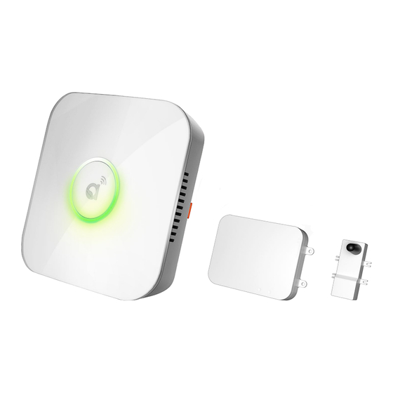
Quick Installation Guide
Autani Manager + RTR + CR05
Autani LLC
7090 Columbia Gateway Drive, Suite 140, Columbia, MD 21046, USA
(443) 320-2233 | (240) 755-0092 (fax) | www.autani.com
This document contains the Proprietary and Confidential Information of Autani, LLC. Any use of this
information without the expressed written consent of Autani, LLC is prohibited. Copyright Autani, LLC
2010-2024. All rights reserved. Please refer to www.autani.com/legal for licensing, intellectual property,
and other legal notices and information.
Advertisement
Table of Contents

Related Manuals for Autani Manager


Summary of Contents for Autani Manager
- Page 1 7090 Columbia Gateway Drive, Suite 140, Columbia, MD 21046, USA (443) 320-2233 | (240) 755-0092 (fax) | www.autani.com This document contains the Proprietary and Confidential Information of Autani, LLC. Any use of this information without the expressed written consent of Autani, LLC is prohibited. Copyright Autani, LLC 2010-2024.
-
Page 2: Table Of Contents
Keilton+autani devices. Presently, commissioning of these devices is managed exclusively by the iOS version the Keilton+autani application. Users may commission Keilton+autani devices before or after installing the Autani Manager with RTR+CR05, bearing in mind that a CR05 is required per Zone and must be added to the 'Zone' through the Keilton+autani application. -
Page 3: Mounting Instructions
2. Mounting Instructions The Autani Manager, RTR and CR05 can be mounted to a ceiling tile or wall and should be mounted within a range of 1000 feet line of sight to the controlling/communication devices, and near a 120VAC wall outlet. When using fixture controllers with the Autani Manager, please consult with Autani support to determine the distance between edge devices and the Autani Manager, as these ranges may vary based on the edge device that is used. -
Page 4: Rtr Dimensions & Connections
2.1.2. RTR Dimensions & Connections Page | 4... - Page 5 2.1.2.1. RTR Dimensions Page | 5...
-
Page 6: Cr05
2.1.3. CR05 Page | 6... -
Page 7: Mounting The Autani Manager Onto A Wall
2.2. Mounting the Autani Manager onto a Wall Position the wall plate on a wall and mark the four mounting holes. Remove the wall plate and pre-drill the mounting holes. Insert wall anchors into the mounting holes, and position the wall plate to align with the mounting holes. - Page 8 Insert the Autani Manager into the groove on the wall plate. It will snap into place. Page | 8...
-
Page 9: Mounting The Autani Manager Onto A Ceiling
2.3. Mounting the Autani Manager onto a Ceiling Position the wall plate on a ceiling tile and mark the four mounting holes. Remove wall plate and pre-drill the mounting holes. Position the wall plate on front of ceiling tile and back plate on back of ceiling tile, aligning the mounting holes. - Page 10 Insert the Autani Manager into the groove on the wall plate. It will snap into place. Page | 10...
-
Page 11: Removing The Autani Manager From Wall Plate
2.4. Removing the Autani Manager from Wall Plate To remove the Autani Manager from the wall plate, press the release tab inward on the wall plate, and then slide the Autani Manager up. Page | 11... -
Page 12: Mounting The Rtr Onto A Wall
2.5. Mounting the RTR onto a Wall Position the RTR on a wall and mark the four mounting holes. Remove the RTR and pre- drill the mounting holes. Insert wall anchors into the mounting holes and position the RTR to align with the mounting holes. -
Page 13: Mounting The Cr05 Onto A Wall
2.6. Mounting the CR05 onto a Wall Position the CR05 on a wall and mark the four mounting holes. Remove the CR05 and pre-drill the mounting holes. Insert wall anchors into the mounting holes and position the CR05 to align with the mounting holes. -
Page 14: Mounting The Cr05 Onto A Ceiling
2.7. Mounting the CR05 onto a Ceiling Position the CR05 on a ceiling tile and mark the four mounting holes. Remove CR05 and pre-drill the mounting holes. Position the CR05 on front of ceiling, aligning the mounting holes. Insert the screws through the CR05 into the mounting holes. Tighten the screws. Page | 14... -
Page 15: Hardware Connections
Installation by a qualified electrician is recommended. Remove the front cover from the Autani Manager to make connections. Press the snap- fit on both sides of the Autani Manager to remove the cover. Page | 15... -
Page 16: Connection To A Power Source
3.2. Connection to a Power Source Connect a power source to the Autani Manager. There are two options: direct power and POE. Surge and Battery Protection Recommended. NOTE: The Autani Manager will power ON the moment power is supplied. In cases where this is not desired, it is recommended to do a safe power-down. - Page 17 POWER OVER ETHERNET (POE) The Autani Manager can be powered using a network switch, POE injector, and an Autani sourced POE splitter. Below are two examples illustrating the connection options with the POE method. NOTE: Using the POE method eliminates the need for an AC outlet near the Autani Manager and is used in place of the provided AC/DC power adapter.
-
Page 18: Connecting Autani Manager To Rtr & Cr05
Wait 15 seconds for the red spinning to go dark. NOTE: Pressing the reset button will turn on the Manager if it was already off. In this case, a second press (after it's fully started) will shut it down. - Page 19 EXT-A port of Autani Manager. (NOTE: Connection at downstream RTR is always on the "back" edge.) NOTE: Do not exceed 50 feet of distance between the RTR and Autani Manager when connecting them via a CAT5E cable. iii. The CR05 is always connected to RTR using CAT5E cable, as shown in the below illustration.
- Page 20 v. The complete connection should look like the below illustration. Page | 20...
- Page 21 Startup Phase: The LED ring will start spinning GREEN clockwise when power is applied. After all the connections are made, install the front cover on the Autani Manager. Press lightly on both sides of the cover to allow the snap-fit pieces to insert into the Autani Manager base. Page | 21...
-
Page 22: Verifying Power And Connectivity Of Autani Manager
4. Verifying Power and Connectivity of Autani Manager 4.1. LED Ring Status Ensure all the connections are made before commissioning the Autani Manager (as explained in the previous section). The LED ring will confirm by displaying a green breathing pattern. The below illustrations describe what each color pattern on the LED ring indicates. -
Page 23: Autani Manager Mac Address Location
4.2. Autani Manager MAC Address Location After remote access has been verified, note the Ethernet MAC for the Autani Manager and install location. Page | 23... -
Page 24: Reset Button Functionality
When the Autani Manager is physically relocated. Remove the front cover on the Autani Manager to use the Reset button. The Reset button is actuated through the hole using a straightened paperclip or similar object. In most cases, a short-press will trigger the OS activity to shut down the Autani ... -
Page 25: Hand-Off
5. Hand-Off 5.1. Commissioning your Devices If your lights have already been commissioned before installing the Manager/RTR/CR05, proceed with adding the CR05s to the commissioned Zones. (Refer to section 5.2. Adding CR05 to a Zone in the Keilton+autani Application.) If your lights have not been commissioned yet, please proceed with downloading the Keilton+autani Application from the following link or QR code. -
Page 26: Adding Cr05 To A Zone In The Keilton+Autani Application
5.2. Adding CR05 to a Zone in the Keilton+autani Application After the Autani Manager/RTR/CR05 has been installed and powered ON, proceed with adding each CR05 to a Keilton+autani Zone. At the bottom of the application, select the "More" menu and then, "Device Info.". Click the "Click to Add"... - Page 27 If multiple CR05 are populating, you may tap a CR05 on the selection screen to flash the blue LED on the CR05 to ensure you are adding the correct/nearest CR05 to the Zone. Once the correct CR05 is identified, tap the grayed out check mark on it. The check mark will turn dark blue.
-
Page 28: Upgrading To Energycenter® And Accessing Your Autani Manager
EnergyCenter®. 5.3.1. Upgrade to EnergyCenter® When your system is ready to be upgraded, please contact support@autani.com and provide the Autani Manager’s Ethernet MAC you recorded in step 4.2. Autani Manager MAC Address Location. 5.3.2. Accessing EnergyCenter® through your Autani Manager Access your system via its local IP address using the default credential admin/password. - Page 29 7090 Columbia Gateway Drive, Suite 140, Columbia, MD 21046, USA (443) 320-2233 | (240) 755-0092 (fax) | www.autani.com This document contains the Proprietary and Confidential Information of Autani, LLC. Any use of this information without the expressed written consent of Autani, LLC is prohibited. Copyright Autani, LLC 2010-2024.
Need help?
Do you have a question about the Manager and is the answer not in the manual?
Questions and answers