Table of Contents
Advertisement
Document: 80309
Revision-01, July 2020
User Manual
Autani CORE/Manager
Autani LLC
7090 Columbia Gateway Drive, Suite 140, Columbia, MD 21046, USA,
(443) 320-2233 | (240) 755-0092 (fax) www.autani.com.
This document contains the Proprietary and Confidential Information of Autani LLC. Any use of this
information without the expressed written consent of Autani, LLC is prohibited. Copyright Autani LLC,
2010-2020. All rights reserved. Please refer to www.autani.com/legal for licensing, intellectual property,
and other legal notices and information.
Advertisement
Table of Contents

Related Manuals for Autani CORE/Manager

Summary of Contents for Autani CORE/Manager
- Page 1 7090 Columbia Gateway Drive, Suite 140, Columbia, MD 21046, USA, (443) 320-2233 | (240) 755-0092 (fax) www.autani.com. This document contains the Proprietary and Confidential Information of Autani LLC. Any use of this information without the expressed written consent of Autani, LLC is prohibited. Copyright Autani LLC, 2010-2020.
-
Page 2: Table Of Contents
2. System Overview .................. 6 3. Mounting Instructions ................8 3.1. Space Requirement ..................8 3.2. Mounting the CORE/Manager onto a Wall ..........9 3.3. Mounting the CORE/Manager onto a Ceiling ..........11 3.4. Removing the CORE/Manager from Wall Plate ......... 13 4. -
Page 3: Core/Manager Overview
CORE/Manager Overview The Autani CORE/Manager appliance is a rugged, industrial control processor that is the heart of innovative integrated energy management systems powered by EnergyCenter® software. The CORE/Manager coordinates all energy management functions utilizing autaniNet wireless, wired Ethernet, and optional wired connectivity to third party systems to securely manage building functions. -
Page 4: Specifications For Core/Manager
Storage: mSATA SSD Color: Autani White/Black Endpoint Capacity: ~120, additional Weight: 1.6 lbs (0.7 kg) endpoints can be added via Autani CORE/Manager add-ons Operating System: Secure Linux-based variant POWER SUPPLY Voltage: 120VAC input / 12VDC output ... -
Page 5: Regulatory Information
Consult the dealer or an experienced radio/TV technician for help. 1.4. Product Warranty 3 year limited warranty from Autani. For further information, please refer to terms and condition on www.autani.com. Autani Support. Phone: 443.320.2233 x2 Address: 7090 Columbia Gateway Drive, Suite 140, Columbia, MD 21046 Support / Commissioning Services: support@autani.com... -
Page 6: System Overview
System Overview SINGLE SYSTEM CONNECTED TO EDGE DEVICES Page | 6... - Page 7 MULTIPLE CORES CONNECTED TO MANAGER Page | 7...
-
Page 8: Mounting Instructions
Mounting Instructions The Autani CORE/Manager can be mounted to a ceiling tile or wall, and should be mounted within a range of 1000 feet line of sight to the controlling/communication devices, and near a 120VAC wall outlet. When using fixture controllers with the CORE/ Manager, please consult with Autani support to determine the distance between edge devices and the CORE/Manager, as these ranges may vary based on the edge device that is used. -
Page 9: Mounting The Core/Manager Onto A Wall
3.2. Mounting the CORE/Manager onto a Wall Position the wall plate on a wall and mark the four mounting holes. Remove the wall plate and pre-drill the mounting holes. Insert wall anchors into the mounting holes, and position the wall plate to align with the mounting holes. - Page 10 Insert the CORE/Manager into the groove on the wall plate. It will snap into place. Page | 10...
-
Page 11: Mounting The Core/Manager Onto A Ceiling
3.3. Mounting the CORE/Manager onto a Ceiling Position the wall plate on a ceiling tile and mark the four mounting holes. Remove wall plate and pre-drill the mounting holes. Position the wall plate on front of ceiling tile and back plate on back of ceiling tile, aligning the mounting holes. - Page 12 Insert the CORE/Manager into the groove on the wall plate. It will snap into place. Page | 12...
-
Page 13: Removing The Core/Manager From Wall Plate
3.4. Removing the CORE/Manager from Wall Plate To remove the CORE/Manager from the wall plate, press the release tab outward on the wall plate, and then slide the CORE/Manager up. Page | 13... -
Page 14: Hardware Connections
appropriate electrical codes and regulations. Installation by a qualified electrician is recommended. Remove the front cover from the CORE/Manager to make connections. Press the snap-fit on both sides of the CORE/Manager to remove the cover. Page | 14... - Page 15 Connect a power source to the CORE/Manager. There are two options: direct power and POE. Surge and Battery Protection Recommended. NOTE: The CORE/Manager will power ON the moment power is supplied. In cases where this is not desired, it is recommended to do a safe power-down. Press and release RESET button and wait around 30 seconds until the LED ring goes dark.
- Page 16 CORE/Manager, and is used in place of the provided AC/DC power adapter. After all the connections are made, install the front cover on the CORE/Manager. Press lightly on both sides of the cover to allow the snap-fit pieces to insert into the CORE/Manager base.
-
Page 17: Commissioning The Core/Manager
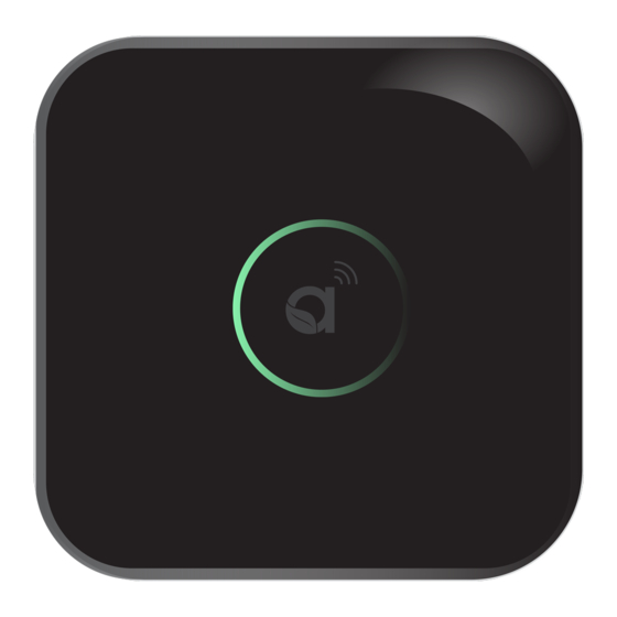
Commissioning the CORE/Manager 5.1. LED Ring Status Ensure all the connections are made before commissioning the CORE/Manager (as explained in the previous section). The LED ring will confirm by displaying a green breathing pattern. The below illustrations describe what each color pattern on the LED ring indicates. -
Page 18: Reset Button Functionality
When the CORE/Manager is physically relocated. Remove the front cover on the CORE/Manager to use the Reset button. The Reset button is actuated through the hole using a straightened paperclip or similar object. In most cases, a short-press will trigger the OS activity to shut down the ... -
Page 19: Selecting A Connection Method
There are two options available to connect the CORE/Manager to a system. Local Area Network (LAN) Access Only In this mode, the CORE/Manager is placed on a Local Area Network (LAN) only and does not have access to Autani’s cloud-based services. This configuration will not support remote access to your facility, nor will Autani personnel be able to directly connect to your devices to help troubleshoot with support issues. - Page 20 Ethernet cable Web browser (Google Chrome & Mozilla Firefox) MAC address of Autani CORE/Manager IP address of the Domain Name System (DNS) server (or one of the free DNS servers available on the web) IP address assigned to the Autani ...
-
Page 21: Local Area Network (Lan) Access
5.3.1. Local Area Network (LAN) Access In this method, the CORE/Manager is connected to a Local Area Network which is connected to other systems. The advantage of this method is that the system can be commissioned without remote access, even before Autani provisions the remote connectivity. -
Page 22: Changing To A Static Ip Address
Remote Access Web Portal. 5.3.1.2. Changing to a Static IP Address By default, the Autani CORE/Manager uses a DHCP assigned IP address when initially connected to a LAN. After accessing the Autani EnergyCenter® software, you have the option of setting a static IP address. - Page 23 Enter the following: • A unique and valid static IP address on the local network A valid netmask • • The default gateway The IP address of your DNS server or use one of the free DNS servers • NOTE: To access the free, Google Public DNS Server, use one of the following IP Addresses: 8.8.8.8 or 8.8.4.4.
-
Page 24: Verifying The Remote Access Capability
5.3.2. Verifying the Remote Access Capability The user can verify if their system can be remotely accessed by following the instructions below. Select Settings > Device Setup > Network Status. The Network Status screen appears, confirming access to the Internet and Remote Portal connection. -
Page 25: Remote Access Via The Worldwide Web
5.3.3. Remote Access via the Worldwide Web In this method, the CORE/Manager is connected to the Internet/Cloud through which the systems are configured. Follow the instructions in this section to perform the Remote Access Configuration. For any issues or problems related to remote access, please contact Autani support (http://www.autani.com/contact/). -
Page 26: Create A New Account
UDP: 54261, 59370, or 59371 TCP: 443 NOTE: For more information, see your IT Administrator. Connect the Autani CORE/Manager Ethernet cable to an active Ethernet port on the LAN. NOTE: For more information, see your IT Administrator. 5.3.3.1. Create a New Account 1. - Page 27 Click the login link. Enter your email address and password, and then click Log in. iii. Select the Autani CORE/Manager with the MAC address in the premise name, and then click the Enable Remote Access button. Click Yes to enable remote access.
-
Page 28: First Time Login To Energycenter® Through Remote Access Web Portal
5.3.4. First Time Login to EnergyCenter® through Remote Access Web Portal 1. Open the browser on your computer. 2. Enter https://www.autani.net/ in the address bar and press enter. 3. The login screen appears as shown below. Enter the credentials provided in the package, and click Log in. - Page 29 5. Wait a few seconds for the Autani CORE/Manager to boot up. When the status is active, the system login screen appears. 6. Log in to the EnergyCenter® software with the same credentials used for the Autani portal. (If win logging in through web portal (autani.net)).
- Page 30 10. Next, follow the instructions provided in 5.4. Accessing EnergyCenter® and Commissioning Devices. 11. If the computer is disconnected from the Autani CORE/Manager, reconnect it for the designated features listed in Table 1: Designated Features. 12. Follow the instructions provided in 5.3.1.2.Changing to a Static IP Address for checking the remote access.
-
Page 31: Using A Usb Stick To Configure Static Network Settings (Optional)
A USB stick can be used to produce and edit the configuration files. There are two USB ports available inside the CORE/Manager. Remove the top cover to access the USB ports. NOTE: The height available for the USB stick insertion is around <2.5”. A small form factor USB stick is recommended, otherwise an extension cable should be used for the regular USB stick. - Page 32 Note that the last line of text in the file will provide the CORE/Manager’s current IP address under DHCP. Using a text editor, the user can follow the instructions in the file to change the networking configuration between DHCP (default) and static. If switching to a static configuration, you must enter the IP address, subnet mask, default gateway, and primary DNS server.
-
Page 33: Accessing Energycenter® And Commissioning Devices
3. Within the Dashboard, click on the Launch link of the premise you wish to access. 4. Log in to EnergyCenter® with the same credentials used for the Autani portal. Page | 33... -
Page 34: Adding Devices For The First Time
5. The EnergyCenter® application is launched, displaying the Devices section by default. 5.4.2. Adding Devices for the First Time To begin adding devices to your system, on the left navigation bar, click Settings > Device Setup > Easy Setup and follow the instructions on the screen. NOTE: For the first device addition, only the “Easy Setup”... - Page 35 If the device is an Autani manufactured device with visible LEDs, color changes indicate the status of the device joining the network. Other third party devices will have different LEDs and different status actions. LED Color Device Status Description When device is powered, it automatically searches for network.
-
Page 36: Example: Label Devices And Assign Locations
5.4.3. Example: Label Devices and Assign Locations Select Devices from the left navigation bar. Click on the applicable tab for your device. From the list of devices, select your device and click on Details. The Details screen appears with the General tab selected. Edit the Name, Description, and Location of the device. -
Page 37: Example: Select Device Settings (Through Details)
The Setup screen appears with the General Settings tab selected. Modify the settings as needed across the tabs. NOTE: For more information, click the Help section on the left navigation bar and select the User Guide specific to the device. 5.4.5. -
Page 38: Example: Associate Sensors With Devices
5.4.6. Example: Associate Sensors with Devices Select Devices from the left navigation bar. Click the applicable device tab, select the desired device, and click Details. The Details screen appears with the General tab selected. Select the Sensors tab and choose the sensors to associate with to your device. -
Page 39: Example: Set Up Email Alert Notifications
NOTE: For more information, click Help on the left navigation bar and select the User Guide Tasks Common to All Applications and, if needed, the User Guide specific to your device. 5.4.8. Example: Set Up Email Alert Notifications From the left navigation bar, select Alerts. The Alert screen appears with the Recent Alerts tab displayed by default. -
Page 40: Troubleshooting
IP address of the Autani Manager/CORE and our web portal at www.autani.net. A port forward may need to be set up between the local IP address of each Autani Manager/CORE on the client’s LAN and the IP address of Autani’s web portal www.autani.net / www.mywebcomfort.net (167.88.116.104 or... - Page 41 Contact Information Autani Support Phone: 443.320.2233 x2 Address: 7090 Columbia Gateway Drive, Suite 140, Columbia, MD 21046 Support/Commissioning Services: support@autani.com Autani Sales Phone: 443.320.2233 x1 Sales/Quotations: sales@autani.com, quotes@autani.com General Inquiries: information@autani.com Hours of Operation: Monday to Friday, 9am to 5pm, Eastern Standard Time...
- Page 42 Intentionally Left Blank. Page | 42...
- Page 43 Intentionally Left Blank. Page | 43...
- Page 44 7090 Columbia Gateway Drive, Suite 140, Columbia, MD 21046, USA, (443) 320-2233 | (240) 755-0092 (fax) www.autani.com. This document contains the Proprietary and Confidential Information of Autani, LLC. Any use of this information without the expressed written consent of Autani, LLC is prohibited. Copyright Autani, LLC, 2010-2020.
Need help?
Do you have a question about the CORE/Manager and is the answer not in the manual?
Questions and answers