
Related Manuals for AURORA SIGNAGE POSTAR II


Summary of Contents for AURORA SIGNAGE POSTAR II
- Page 1 Intelligent HD LED Display Ⅱ POSTAR P r o d u c t M a n u a l Tel: 1300 841 542 PROFESSIONAL · CAPTIVATING · INNOVATIVE Web: www.aurorasignage.com.au...
-
Page 2: Table Of Contents
CONTENTS 1. Preface ................03 3.1.3Standard Parts List ........... 1.1Manual Description...........03 3.2 Module Installation ............1.2 Safety Precautions ........... 03 3.3 Start Up ................2. Product Introduction............04 4. ClassicApplications ............... 2.1 Product Application ..........04 4.1 Internal Signal and Power Supply Connection ....2.2 Product Features ............. - Page 3 5. Software Operating Instructions ........7. Warranty and After-sales Service ........... 5.1 PCMaterial Publish ........... 7.1Warranty Policy ..............5.2 Mobile Phone Material Publish ....... 7.2 After-sales Service............5.3 Modify Configuration File ........8. Special Statement ..............5.3.1 Import .rcfg File ..........5.3.2 Import .scr File..........
-
Page 4: Preface
LEDpanels and efficient experience with POSTAR II. manufacturer-approved parts; 2) This manual takes the POSTAR II1.9mm as an example to make the ·... -
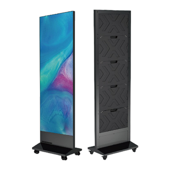
Page 5: Product Introduction
· If the product has abnormal situation, such as odor, smoke, leakage, POSTAR II series can be widely used in retail store, hotel, restaurant, shopping abnormal temperature, please immediately cut off the power supply, and mall, bank, company, hospital, school, airport, subway station and etc. to provide efficient display service. -
Page 6: Product Composition
2.3 Product Composition POSTAR II series intelligent HD LED Poster mainly contains 5 LED display panels, 1 set foot-mounting components, and 1 control box, more details are shown in below: No. Name Components LEDdisplay panel 5 panels in 1 row and 5 columns... -
Page 7: Product Size
2.4 Product Size 2.5 Port Instructions 610.0 41.5 Power supply input port On/Off button Audio port WLAN port LEDOUTNetwork port Patch antenna 400.0 609.0 Display Size 610×1716mm Screen Size 616×2060×400mm Tel: 1300 841 542 PROFESSIONAL · CAPTIVATING · INNOVATIVE Web: www.aurorasignage.com.au... -
Page 8: Specifications And Parameters
2.6 Specifications and Parameters 2.6.1 LEDPoster Specifications SPECIFICATIONS POSTAR Ⅱ 1.5-72" POSTAR Ⅱ 1.9-72" POSTAR Ⅱ 2.5-72" Pixel Pitch(mm) 1.588 1.906 2.542 LED Type Brightness(cd/m Refresh Rate(Hz) 1920/3840 1920/3840 1920/3840 Power Consumption 720/240 510/180 480/168 (Max/Ave) (W/display) Panel Resolution(px) 384×216 320×180 240×135 Panel Size(mm) -
Page 9: Receiving And Start Up
3. Receiving and Start Up 3.1.3Standard Parts List 3.1 Receiving 3.1.1Packing Instructions (optional flight case shown) Flight cases(size:2300*600*850mm, weight:130kg) packing, 2 POSTAR in one case(including base and wheels). 3.1.2Unpacking Instructions Module Bridge Board+ Receiving Card 2 Pcs 1 Pcs ②Take out structure, module and poster parts cartons USB Key... -
Page 10: Module Installation
3.2 Module Installation Note: · Glovesshould be worn in the installation process, and no forced assembly shall be allowed. · Module installation sequence can be from left to right, from right to left, from top to bottom or from bottom to top. ·... -
Page 11: Classicapplications
4. ClassicApplications 4.2 Stand-alone Device Display Application 4.2.1Stand-alone Device Display Application Via Built-in Player 4.1 Internal Signal and Power Supply Connection Signal cable Cable (TIA/EIA 568B) Power cable with 4 branches Above is a POSTAR wiring diagram in built-in player mode. Player lists can be imported by connecting the network to the computer. -
Page 12: Stand-Alone Devicedisplayapplication Via Cloudplatform
4.2.2 Stand-alone PCDisplay Application Via LAN 4.2.3 Stand-alone PCDisplay Application Via Cloud Platform The diagram above is a multi-POSTAR networking system connection based The screen can be connected to the Internet through Wi-Fi/cable, and on LAN. The program list is sent to each POARAR by using the playback screens in different areas can be controlled and managed by remote management software. -
Page 13: Multi-Units Cascade Extended Display Application
④ Connect three POSTAR in turn and insert dowel pins to lock adjacent two 4.3 Multi-units Cascade Extended Display Application 4.3.1 Multi-units Splicing Installation modules, and then fix the side lock with wrench. Taking three POSTAR splicing as an example, the following steps can be used to illustrate the splicing method for more than three POSTAR: ①... -
Page 14: Multi-Units Splicing Wiring(Inside Power Box)
⑤ Install all modules refer to steps in “3.2 Module Installation” 4.3.2 Multi-units Splicing Wiring(Inside Power Box) ① Remove two screws from the back cover of each POSTAR power box and remove the back cover; ② Pull out cables of the latter two POSTAR LED IN ports and connect cables to the LED OUT port of front one in turn;... -
Page 15: Multi-Units Splicing System Connection
4.3.3 Multi-units Splicing System Connection 2) 3 Units Cascade Application 1) 2 Units Cascade Application Cable Cable LED IN LED IN LED OUT LED OUT LED OUT LED IN Connect to PC Power IN Power IN Power IN Connect to PC Power IN Power IN Note: POSTAR 1.9-72″... - Page 16 3) 4 Units Cascade Application Cable LED OUT LED OUT LED OUT LED IN LED IN LED IN Connect to PC Power IN Power IN Power IN Power IN Note: POSTAR 2.5-72″ can support 4 units cascade extended display with POSTAR built-in (T3) player. Tel: 1300 841 542 PROFESSIONAL ·...
-
Page 17: External Device Extended Display Application
4.4 External Device Extended Display Application LED OUT LED OUT LED OUT LED OUT LED IN LED IN LED IN LED IN Connect to PC Power IN Power IN Power IN Power IN Power IN Splicing application for more than one POSTAR 1.5-72″, two POSTAR 1.9-72″ and four POSTAR 2.5-72″ shall need external players. TB50 or TB60 external players can be selected according to splicing resolution. -
Page 18: Software Operating Instructions
5. Software Operating Instructions 2) Network Connection ② Open PCWLAN and connect POSTAR Wi-Fi, see Diagram 5.3; · Network Name: Apxxxxxxxx (for example:AP10000033) 5.1 PCMaterial Publish · Network Password: 12345678 1) Software installation Note: The network name of each POSTAR is marked on the back cover of ①... - Page 19 Step 8 Step 2 Note: The standard resolution of each POSTAR II 1.5-72" must be set to 384*1080, the standard resolution of each POSTAR II 1.9-72″ must be set to 320*900, and the standard resolution of each POSTAR II 2.5-72″ must be set to 240*675.
- Page 20 ④ According to the number of materials click on the [+] add pages, each page can choose to add text, pictures, videos, motion pictures and other format materials, as shown in Diagram 5.6. Step 9 Diagram 5.6 Tel: 1300 841 542 PROFESSIONAL ·...
-
Page 21: Mobile Phone Material Publish
5.2 Mobile Phone Material Publish 2) Network Connection ① Open mobile phone WLAN and connect POSTAR Wi-Fi; 1) Mobile Phone App Installation Network Name: Apxxxxxxxx (for example:AP10000033) a) Android system mobile phone: Network Password: 12345678 Scan the QRcode below, download the Viplex software installation package and install it. - Page 22 Note: The standard resolution of each POSTAR II 1.5-72" must be set to ② Open ViPlex Handy, find corresponding POSTAR and connect as shown in 384*1080, the standard resolution of each POSTAR II 1.9-72" must be set to Diagram 5.8.
-
Page 23: Modify Configuration File
5.3 Modify Configuration File 5.3.1 Import .rcfg File ① Open Wi-Fi switch on PC, search an connect POSTAR Wi-Fi hotspot( user Note: Configuration files (. rcfg files and. scr files) shall be modified for name: admin, initial password: 12345678); more than one units cascade application. ②... - Page 24 ④ Import *.rcfg file; ⑥ Send and save .rcfgx file; ⑤ ISelect*.rcfgx file in the corresponding folder according to application mode Tel: 1300 841 542 PROFESSIONAL · CAPTIVATING · INNOVATIVE Web: www.aurorasignage.com.au...
-
Page 25: Import .Scr File
5.3.2 Import .scr File According to the application mode, select the *. scr file in the Note: Only after clicking “Save to Screen”,the settings can come to effect. At the same time, the image will be played according to the actual screen size. -
Page 26: Maintenance Instructions
6. Maintenance Instructions 6.1 Common Faults and Troubleshooting Malfunction Malfunction Analysis Solution 1. The power adapter is not plugged in correctly; 1. Checkthe power adapter and on/off button; whole screen fails 2. The on/off button is not turned on; 2. Replace the malfunctioning controller. 3. -
Page 27: Parts Replacement
6.2 Parts Replacement 6.2.2 Replacing Bridge Board( or Receiving Card) All of following parts must be operated in the power-off state for your safety. Step Diagram Method 6.2.1 Replacing Module Remove all LEDboards from the faulty cabinet. Step 1 Step Diagram Method Place the front maintenance... -
Page 28: Replacing Controller(Or Power Supply)
6.2.3 Replacing Controller(or Power Supply) 8. Special Statement The controller and power supply are installed under the power box. Refer to the step of "4.3.2 Multi-units Splicing Wiring (in Power Box)" to remove 1) Intellectual Property Rights Statement: The hardware design and the back cover of the power box and replace the controller and power software program of this product are protected by copyright, and any supply.
Need help?
Do you have a question about the POSTAR II and is the answer not in the manual?
Questions and answers