
Related Manuals for AURORA SIGNAGE LDC610 SFP II Series


Summary of Contents for AURORA SIGNAGE LDC610 SFP II Series
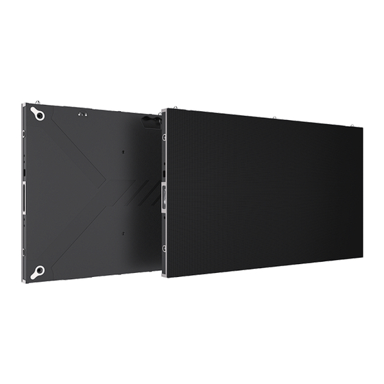
- Page 1 LDC610XXSFP Series II Display Product All pictures in this manual are for reference only, and the details shall be subject to the real ones User Manual Product type: LED small pitch products File version: V2.1...
-
Page 2: Table Of Contents
Contents 1. Product Introduction ......................6 1.1 Product Features ......................6 1.2 Product Dimension ....................... 7 2. Product Components ......................7 2.1 Cabinet Structure ......................7 2.2 Wring Hole Location ..................... 8 3. Product Assembly ........................9 3.1 Install wall-mounting bar ....................9 3.2 Assemble cabinets ...................... - Page 3 This manual takes the LED small pitch products customized project as the example to systematically introduce the product components, ports, specifications, as well as installation, function applications and other instructions, aiming at guiding user to start an efficient experience with the LED small pitch products;...
- Page 4 NOTE ! It is highly probable that you will not be able to get the best display effect if you ignore the content of the notice. 1) Wear anti-static gloves and anti-static bracelet during installation and maintenance; 2) Smooth air flow on the back of the display must be considered when designing the heat dissipation scheme;...
- Page 5 Construction precautions! 1) With a laser level, a tape measure, a plane measuring sling, a hole drilling tool, etc; 2) After arriving at the site, check whether the length, width, thickness and wiring quantity and type of the reserved size are within the reserved standard; 3) If there is no steel structure back frame, the height from the ground must be confirmed with the user, and the center position must be marked;...
-
Page 6: Product Introduction
1. Product Introduction 1.1 Product Features 1) Shunt power supply technology, green energy saving 2) Ultra slim and light-weight design, 4.8kg cabinet with 31mm thickness; 3) Fully front-access maintenance mode supports hot swapping and quick repair; 4) 3-in-1 integrated design without wiring ensures stable performance; 5) It can support 800 nits brightness to meet the needs of commercial display scenes 6) High-integrated 5-in-1 hub-board technology, power supply &signal... - Page 7 13) Calibration data is stored in display module, enabling calibration data auto reading function after module replacement; 14) The series satisfies RoHS environmental protection requirements both in China and EU.
-
Page 8: Product Dimension
1.2 Product Dimension 2. Product Components 2.1 Cabinet Structure Upper and Lower Hook Lock Upper and Lower Dowel Pin Left and Right Spring Dowel Pin Left and Right Hook Lock Hook Mounting Hole(M8) Connection Plate Mounting Holes(M8) -
Page 9: Wring Hole Location
2.2 Wring Hole Location Upper Signal Cable Wring Hole Upper Power Cord Wring Hole Left and Right Reserved Wiring Hole Lower Power Cord Wring Hole Lower Signal Cable Hole... -
Page 10: Product Assembly
3. Product Assembly 3.1 Install wall-mounting bar Locate the positions to drill holes for upper and lower wall-mounting bars according to onsite environment and distance requirement between screen and floor, and use level instrument to ensure position precision; The upper and lower wall-mounting bars are respectively composed of the wall-mounting bar 1 and the wall–mounting bar 2, which are joined by connection plates. - Page 11 align wall-mounting bars to holes drilled in previous step and fix bars with M8* 80 expansion bolts as shown below: Outer Hexagonal Screw Thickening Anti-slip Thickening Washer Bushing Side profile diagram of installed wall-mounting bar: Load-bearing Wall Wall-mounting Bar M8*80 Expansion Bolt(fixed to the wall) Front view diagram of installed wall-mounting bars: Upper Wall-mounting Bar Lower Wall-mounting Bar...
-
Page 12: Assemble Cabinets
1)Use a level instrument to measure the horizontalness of wall-mounting bar. If it is not horizontal, make adjustment by loosening the expansion bolt and gently pushing wall-mounting bars. And then tighten the wall-mounting bar with screws. 2)Use a tape measure to check the spacing between the upper and lower rows of wall-mounting bars. - Page 13 Use 2 M28*25 hexagon head bolts and flat spring washers to fix hooks to cabinets, and remove dowel pins of cabinet assembled on the top, and spring dowel pins of the leftmost cabinet column in front view, and then fix cover strips with cross point screwdriver as shown below: Place cabinet columns in order and align spring dowel pins to holes on two sides of each column, and then fix cabinet columns side locks with inner hexagon...
-
Page 14: Assemble Left/ Right / Top Cover Strip
Screen wiring: As shown in below diagram, red indicates power cord branch, and purple indicates signal cable branch, connect power cords and signal cables between cabinets. 3.3 Assemble Left/ Right / Top Cover Strip Left and right cover strips shall be assembled into side spring dowel pin hole by buckles in front view (remove the spring dowel pins on the leftmost cabinet column). -
Page 15: Assemble Modules
3.4 Assemble Modules * Modules shall be installed according to numbers from left to right, right to left or bottom to top, top to bottom, depending on the installation environment. * Make sure that the flatness of the installed module is qualified and make adjustment during the process. - Page 16 that it is the module installed in cabinet No. 4 during factory calibration, and number 8 represents the position of this module in cabinet No. 4. Front View Below diagram shows the finished effect of a whole screen.
-
Page 17: Control System
4. Control System 4.1 Input Voltage Requirement The input voltage should be 110V/220/土 10%, frequency 50HZ~60HZ, consisting with the display power supply voltage. 4.2 Controller Paramenter (1) Controller Description LED small pitch products customized project comes standard with the CRN PCON 200 Pro controller, which is a built-in Android operation system, supporting 2-way HDMI external inputs and synchronous or nonsynchronous controller with 6-way RJ45 gigabit network port outputs. - Page 18 Name Function Power-off state: short press to turn on Standby state: short press to wake up the screen Power button Power-on state: short press to start standby mode (rest screen) Power-on state: long press for 3-5 seconds to turn down Front Panel Input Port Type...
- Page 19 AUDIO OUT 3.5mm audio output port WAN port, can be connected to the host computer or LAN/public network to conduct program publishing and screen control RELAY OUT Extended port, used for ON/OFF control, and etc. RS-485 Protocol port, used for brightness sensor connection Can be connected to the central control system, and RS232 used for multi-units cascade application...
-
Page 20: System Connection Diagram
screen information configuration and displaying effect adjustment 4.3 System Connection Diagram System connection diagram is shown below: Single-device Connection Multi-device Connection Note: When the wireless network is connected, user shall manually open CRN PCON 200 Pro Wi-Fi switch, and meanwhile the Wi-Fi AP hotspot will be turned off automatically. -
Page 21: Safety Precautions
other devices firstly, and then turn other devices on. 4.4 Safety Precautions Before the screen is powered on, the cables connection between cabinets, main cables and other cables must be checked without wrong connection, reverse connection, short circuit, circuit break, loosening, etc., and tested with multimeter and other tools. - Page 22 named【Software】, and install MaxConfig.exe control software as shown below: (2) Screen Configuration Load corresponding configuration files through MaxConfig to configure screen. The MaxConfig software is divided into two operating modules: Screen On Wizard and Professional Debug. Screen On Wizard (1) Operation steps: Step 1: Enter the interface to connect the transmitter card, send the transmitter card FPGA and HDMI parameter files...
- Page 23 Step 2: Set the number of rows and columns of cabinets and the resolution of single cabinet Step 3: Set the Ethernet port for cabinet and connection relationship, and click Send to send the cabinet set parameters Step 4: Import LED panel parameters, Gamma parameters, and complete screen light on...
- Page 24 Function introduction Transmitter card Supported functions: 1) Transmitter card list; 2) System version upgrade; 3) System settings Connection relationship editing Supported functions: 1) Connection relationship setup; 2) Screen pop-up, select, screen adaptation, reset, clear connection, delete empty cabinet, connection relationship reading, send, import, export;...
- Page 25 Gamma settings; 4) Receiver card information list; 5) Monitoring information. Professional debugging Go the main interface, click “Help” to bring up the main menu of software information (the help menu includes language settings and software version information). The software menu is displayed as follows: 1) Language 2) After the software is installed, the system automatically selects the corresponding language based on the operating system.
- Page 26 Screen Mode When the MaxConfig software is opened, the software interface is displayed as follows: Software Functions List: Function Name Function Description Screen, transmitter card section 1. Display the connection status and LED product information, Product including signal and software version; 2. Software upgrade and information calibration related settings Input source...
- Page 27 Others Set module parameters, HDMI settings, brightness strategy Set main control to achieve synchronous adjustment of Group control brightness, contrast, color temperature Transmitter card Computer out test mode or device out test mode, and advanced – test mode test mode Preset saving Custom split screen preset saving Receiver card...
- Page 28 spacing Backup System loop backup Calibration Enable calibration Enable calibration function. Refresh data Save the LED panel calibration data to the cabinet bridge board Cabinet Send single cabinet calibration data calibration data Full screen Send full screen calibration data calibration data Calibration data Provide the capability to specify the starting point and size of the sending position...
-
Page 29: Common Functions
5. Common Functions 5.1 Start up Plug in the power supply; Press the one-button start up button on the bottom of the control unit to wait for a few seconds and then the display will automatically enter the main interface. 5.2 Main UI The Welcome, which contains built-in templatesand welcome themes;... - Page 30 applications. (1) Welcome Interface It contains built-in multi-style templates in which pictures and welcoming words can be customized, and style, color, location and others of text can be modified, which make the creation of welcoming words simpler and more creative; (2) Screen Share MAC or Windows system computer, mobile phone, tablet device can realize screen share function on the all-in-one display.
- Page 31 Computer Screen Share MAC System Device Wireless Screen Share Connect the all-in-one LED display Wi-Fi hotspot. Name:LED_AIO_917e Password:12345678 Follow the instructions and video demonstration in the MAC User Guide of the wireless screen share interface, as shown below: Windows System Device Wireless Scree Share Download and install the screen assistant application software.
- Page 32 Mobile Phone Screen Share Android system mobile phone Connect the all-in-one LED display Wi-Fi hotspot. Name:LED_AIO_917e Password:12345678 Scan the following QR code to download the mobile app screen assistant.(Note: This step is required for the first time. If you already have the APP, you can skip this step).
- Page 33 Open the Screen Assistant and start to share screen, as shown below: Scan QR code and then click mirroring to select AndroidAP to start screen sharing, as shown below: Note:select screen sharing link if there is no QR code. iOS system mobile phone: Pull out the menu from the bottom of the phone, click on the Screen Mirroring to select LED_AIO_917e,and start to screen mirroring, as shown below:...
- Page 34 Multi Terminals Simultaneous Screen Share First, one terminal (such as a mobile phone, a tablet, or a computer) completes the screen share operation, and another terminal (computer) shall be inserted into the wireless screen transmitter and long-pressed to realize multi terminals screen sharing simultaneously.
-
Page 35: Usb Input
Open Explorer to start file management; If the device has been connected to the USB flash drive, user shall find corresponding one to read file. (4) More Applications The product has built-in video player, image gallery and other software, which can play pictures or video files come with original system or in the USB flash drive. -
Page 36: Hdmi Input Connection
5.4 HDMI input connection Connect a device having the HDMI output such as a computer by an HDMI cable; Press channel switch button (on the machine or remote control) to switch to HDMI display channel. Note: common HDMI cable transmission distance shall be less than 5 meters. Apply fiber HDMI cable for long distance transmission. - Page 37 (2)Picture Quality Setting Select “picture quality” setting by remote control or find it in the “menu” option on the MaxConfig mobile application-remote control function. Set scene mode, brightness, contrast, color temperature and aspect ratio to achieve ideal picture quality for various application scenarios by “OK” and “Up & Down” buttons on the remote control, or option bars on MaxConfig setting page.
- Page 38 (4)Color Temperature Setting Select “color temperature” by remote control or find it in the “picture setting” of “menu” option on the MaxConfig mobile application-remote control function. Enter the page to select nature, design, warm color, cold color and user mode for onsite needs by “OK”...
- Page 39 (5)Menu Setting Select “menu setting” by remote control or find it in the “menu” option on the MaxConfig mobile application-remote control function. Enter the page to select language, menu horizontal position and menu vertical position for onsite needs by “OK” and “Up & Down” buttons on the remote control, or option on MaxConfig setting page.
- Page 40 MaxConfig mobile application-remote control function. Enter the page to select volume, mute and reset for onsite needs by “OK” and “Up & Down” buttons on the remote control, or option on MaxConfig setting page. Select “volume” to adjust sound volume according to application scenarios. Shortcut button can also be found on the remote control.
-
Page 41: Common Hardware Faults Troubleshooting
6. Common Hardware Faults Troubleshooting (1) Partial screen is black after power on Check whether the network cable inside the cabinet is disconnected or in loose contact. ② Check whether the power cord inside the cabinet is disconnected or in loose contact. -
Page 42: Parts Replacement
7. Parts Replacement 7.1 2-in-1 Board Replacement Step Diagram Method Find location of fault Step 1 cabinet and remove all modules. Disconnect cables Step 2 and power cords. Remove screws on Step 3 the 2-in-1 board. Replace a new board and fix it to the cabinet with screws. -
Page 43: Module Replacement
7.2 Module Replacement Step Diagram Method Find specific location fault module, and place Step 1 the side surface of maintenance tool just below module. Rotate the front maintenance tool upward and slowly transition from the Step 2 arc surface to the bottom. - Page 44 Hold the module with full palm and rotate the Step 3 maintenance tool away from the module surface. Note that the arrow direction is upward Step 4 when installing a new module back.
-
Page 45: Special Statement
8. Special Statement Intellectual Property Rights: The hardware design and software programs of this product are protected by copyright. The contents of this product and the manual shall not be copied without the authorization of the company. The contents of this manual are for reference only and do not constitute a ...
Need help?
Do you have a question about the LDC610 SFP II Series and is the answer not in the manual?
Questions and answers