Table of Contents
Advertisement
Quick Links
REGISTER YOUR PRODUCT FOR WARRANTY
www.fgwilson.com/warranty
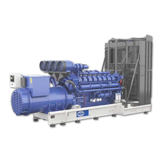
FG Wilson Generator Set
Operator & Maintenance
Instruction Manual
This manual has been designed as a guide to operators to aid in starting, stopping and otherwise safe operation of
FG Wilson P Series and PRO rental series of generator sets.
ORIGINAL INSTRUCTIONS
356-5901(GB) V15 10/21
Advertisement
Table of Contents
Troubleshooting

Subscribe to Our Youtube Channel
Related Manuals for FG Wilson P Series

Summary of Contents for FG Wilson P Series
- Page 1 Operator & Maintenance Instruction Manual This manual has been designed as a guide to operators to aid in starting, stopping and otherwise safe operation of FG Wilson P Series and PRO rental series of generator sets. ORIGINAL INSTRUCTIONS 356-5901(GB) V15 10/21...
- Page 2 356-5901(GB) V15 10/21...
-
Page 3: Table Of Contents
CONTENTS 1. INTRODUCTION 2. SAFETY 2.1 General ........................................7 2.1.1 Emergency Stop Button ....................................7 2.2 Personal Protective Equipment .................................7 2.3 General Hazard Information ................................8 2.3.1 Pressurized Air and Water ....................................8 2.3.2 Containing Fluid Spillage ....................................8 2.3.3 Lines, Tubes and Hoses ....................................8 2.3.4 Disposal of Waste ...................................... - Page 4 4.3 Moving the Generator set ................................. 27 4.3.1 Approved Lifting Methods for ISO Walk-in Containers ........................31 4.3.2 Approved Lifting Methods for Non-ISO Walk-in Containers ......................31 4.4 Foundations and Vibration Isolation............................. 32 4.4.1 Foundation ........................................32 4.4.2 Vibration Isolation ......................................32 4.5 Storage ........................................33 4.5.1 Engine Storage ........................................33 4.5.3 Battery Storage .......................................33 4.5.4 Aftertreatment Systems Storage ................................33...
- Page 5 5.6 Control System Options and Upgrades ............................64 5.6.1 Battery Trickle / Auto Boost Chargers ..............................64 5.6.2 Heaters ..........................................64 5.6.3 Electric Fuel Transfer Pumps ..................................64 5.6.4 Meters / Gauges ......................................65 5.6.5 Speed / Voltage Control ....................................65 5.6.6 Alarm Signalling ......................................65 5.6.7 Automatic Preheat Control ..................................65 5.6.8 Remote Annunciator Panels ..................................65 6.
-
Page 6: Introduction
1. INTRODUCTION Thank you for choosing our company to supply your electrical power needs. In line with our policy of continuous product improvement, we reserve the right to change the information contained within this manual without notice. This Operator Instruction Manual has been designed to help you operate and maintain your electrical generator set correctly. We recommend that the operator should take the time to read this manual. -
Page 7: Safety
2. SAFETY 2.1 General The generator set is designed to be safe when used in the correct manner. Responsibility for safety, however, rests with the personnel who use the set. Before performing any procedure or operating technique, it is the user’s responsibility to ensure that it is safe to do so. -
Page 8: General Hazard Information
• Ensure that all protective guards and all covers are secured in place on the engine. • Never put maintenance fluids into glass containers. Glass containers can break. • Use all cleaning solutions with care. • Report all necessary repairs. Unless other instructions are provided, perform the maintenance under the following conditions: •... -
Page 9: Disposal Of Waste
2.3.4 Disposal of Waste Improper disposal of waste can threaten the environment. Potentially harmful fluids should be disposed of according to local regulations. Always use leakproof containers when you drain fluids. Do not pour waste onto the ground, down a drain, or into any source of water. 2.4 Fire and Explosion All fuels, most lubricants, and some coolant mixtures are flammable. -
Page 10: Exhaust Gases
2.5 Exhaust Gases Always start and operate the engine in a well-ventilated area. If the engine is in an enclosed area, vent the engine exhaust to the outside. Warning Engine exhaust contains products of combustion which may be harmful to your health. 2.6 Mechanical The generator set is designed with guards for protection from moving parts. -
Page 11: Noise
2.8 Noise Sound levels will vary depending on the configuration of the generator set and the final installation of the generator set. Refer to the following for factors that influence the level of exposure: • The characteristics of the area around the generator set •... -
Page 12: Battery Disconnect Switch
2.9.3 Battery Disconnect Switch Turn off the battery disconnect switch to disable the entire electrical system. Generator sets with DEF fluid systems are equipped with a “Wait to Disconnect” lamp. When the engine stops, this lamp will remain illuminated while the system performs operations such as purging the DEF lines. The battery disconnect switch should not be opened until the “Wait to Disconnect”... -
Page 13: First Aid For Electric Shock
The information below applies to only the product configurations that contain regional product marking on or near the Product Identification Plate. Sound Level Regions Engine Model Maximum Guaranteed Value (GV) dB(A)(1)(2) European Union 400 Series - 6.8 - 24 kVA United Kingdom 1100 Series - 24 - 220 kVA Eurasian Economic Union... -
Page 14: Engine & Aftertreatment
IF NO BREATHING AND NO PULSE: 11. Call or telephone for medical help. 12. Give two breaths and start chest compression as follows: 13. Place heel of hand 2 fingers breadth above ribcage/breastbone junction. 14. Place other hand on top and interlock fingers. 15. -
Page 15: Coolant
2.12.3 Coolant When the engine is at operating temperature, the engine coolant is hot. The coolant is also under pressure. The radiator and all lines to the heaters or to the engine contain hot coolant. Any contact with hot coolant or with steam can cause severe burns. Allow cooling system components to cool before the cooling system is drained. -
Page 16: Hazard Label Legend
2.13 Hazard Label Legend Ensure that all of the safety messages are legible. Clean the safety messages or replace them if the words cannot be read or if the illustrations are not visible. Use a cloth, water and soap to clean the safety messages. Do not use solvents, gasoline, or other harsh chemicals as these could loosen the adhesive that secures the safety messages. - Page 17 X Kg (X LBS) Warning - Four Point Lift is Rated at ’X’ kg Do Not Lift Symbol Read the manual No Naked Flames Battery Acid Explosive Gas Do NOT Powerwash Take note of operating Positive & Negative Earth instructions Electric Terminals Desel Fuel - Read the manual...
-
Page 18: General Description
3. GENERAL DESCRIPTION This generator set has been designed as a complete package to provide superior performance and reliability. Each generator set is provided with a Rating Plate generally affixed to the alternator housing / panel enclosure. This label contains the information needed to identify the generator set and its operating characteristics. This information includes, but is not limited to, the model and serial numbers, output characteristics such as voltage, phase and frequency, output rating in kVA and kW and rating type (basis of the rating). -
Page 19: Typical Pin Plate
The Product Identification Number (PIN) will be used to identify a powered machine that is designed for an operator to ride. FG Wilson products such as engines, transmissions and major attachments that are not designed for an operator to ride are identified by Serial Numbers. For quick reference, record the identification numbers in the spaces that are provided below the illustrations. -
Page 20: Declaration Of Conformity (European Union)
Generic Denomination Power Generating Function Generator Set Model Pxxx-x Serial Number FGWxxxxxxxxxxxxxx Commercial name FG WILSON fulfils all the relevant provisions of the following Directives EU Directive Notified Body Document No. 2006 /42 /EC 2014/35/EU 2014/30/EU 2011/65/EU 2000 /14 /EC amended by... -
Page 21: Declaration Of Conformity (Great Britain)
Power Generating Function Generator Set Model Pxxx-x Serial Number FGWxxxxxxxxxxxxxx Commercial name FG WILSON fulfils all the relevant provisions of the following Directives Approved Body Document No. Great Britain Legislation 2008 No. 1597 2016 No. 1101 2016 No. 1091 2012 No. 3032 2001 No. -
Page 22: Generator Set Description
3.5 Generator set Description 2222 356-5901(GB) V15 10/21... -
Page 23: Power Factor
3.6 Power Factor Power factor (PF) is the ratio of real power to apparent power. The real power is also known as the active power, or kW. The apparent power is also called kVA. Real power (kW) is the mechanical power output of the engine converted to electrical energy, consumed by the load. -
Page 24: Installation, Handling And Storage
4. INSTALLATION, HANDLING AND STORAGE 4.1 General This section discusses factors important in the effective and safe installation of the generator set. Selecting a location for the generator set can be the most important part of any installation procedure. The following factors are important in determining the location: •... -
Page 25: Outdoor Installation
4.2 Outdoor Installation Installation and handling is greatly simplified when the generator set has been equipped with an enclosure. Two basic types may be fitted. The first type is a close fitting canopy enclosure. This will be both weatherproof and sound attenuated. The other enclosure type is a walk-in type container, similar to a shipping container. -
Page 26: Positioning Of Walk-In Containers
4.2.1 Positioning of Walk-in Containers Proper installation of the container is required if successful generation of power is to be achieved. The following information must be considered in the selection of the operating site for the container. The containerised generator set must be placed on a flat surface in order to maintain proper alignment. -
Page 27: Moving The Generator Set
4.3 Moving the Generator set Prior to any movement or installation of the generator set please review the following steps Keep all non-essential personnel clear of the area. Load the package and unload the package on a level surface. Block the transport vehicle so the vehicle cannot move. Keep both the trailer bed and the ramps for the trailer clean. - Page 28 1. Forklift Pockets 2. Oil FIeld Skid Figure 4.5 – Typical generator set with Oil Field Skid base option If the generator set will be regularly moved, it should be fitted with the optional Oil Field Skid which provides forklift pockets in the base frame along with eyes for pulling.
- Page 29 1. Single Point Lift Figure 4.6 – Single Point lift Figure 4.7 – Two Point lift Warning Please ensure the fuel tank is empty when lifting the generator set to ensure safe and stable lifting. Centre of gravity decal is located on the base / canopy of the generator set. The centre of gravity may not always be located at the centre of the generator set.
- Page 30 1. Spreader Bar Figure 4.8 – Proper lifting arrangement for installing the generator set (open & enclosed) 3030 356-5901(GB) V15 10/21...
-
Page 31: Approved Lifting Methods For Iso Walk-In Containers
4.3.1 Approved Lifting Methods for ISO Walk-in Containers Containers are manufactured to ISO dimensions, ISO 1496–4:1994(E) and ISO 668:1995(E). To ensure the safety of all personnel involved with the handling of containers, it is important that the correct lifting and handling procedures are employed. The procedures detailed below are derived from ISO 3874:1997(E) and must be followed at all times. -
Page 32: Foundations And Vibration Isolation
4.4 Foundations and Vibration Isolation The generator set is supplied on a rigid base frame that precisely aligns the alternator and engine and needs only be bolted down to a suitably prepared surface. 1. Vibration Isolators 2. Flexible Exhaust Coupling 3. -
Page 33: Storage
Before storage of the generator set please perform all required maintenance as recommended. For storage periods greater than one year please contact your local FG Wilson dealer for proper storage instructions. 4.5.1 Engine Storage The engine should be put through an engine “preservation”... -
Page 34: Expected Life
Service hours to engine overhaul or replacement may vary based on overall machine duty cycle. At the expected life interval, remove the machine from operation and consult your FG Wilson dealer for inspect, repair, rebuild, install remanufactured, install new components, or disposal options and to establish a new expected life interval. If a decision is made to remove this machine from service please also consult your FG Wilson dealer •... - Page 35 Perform any necessary repairs as soon as possible. Overall Machine Machine service is required. Monitoring System displays Stop the engine immediately. Warning Category 3 Contact your local FG Wilson dealer 3535 356-5901(GB) V15 10/21...
-
Page 36: Control System Description And Trouble Shooting
5. CONTROL SYSTEM DESCRIPTION AND TROUBLE SHOOTING 5.1 Control System Description An electronic control system has been designed and installed to control and monitor the generator set. Depending on the requirements of the generator set, one of several different standard control systems may be fitted. Other more specialised systems may be fitted for specific installations in which case separate documentation is provided. - Page 37 Warning Before tightening the fan belts, disconnect the battery negative (–) lead to ensure the engine cannot be accidentally started. 4. Check the condition and tension of the fan and engine alternator belts – tighten as necessary. 5. Check all hoses for loose connections or deterioration – tighten or replace as necessary. 6.
-
Page 38: Powerwizard 1.1, 1.1+ & 2.1 (Quickstart)
5.2 PowerWizard 1.1, 1.1+ & 2.1 (Quickstart) 5.2.1 General Information Figure 5.1 – PowerWizard Control System Panel The controller is available in three versions, PowerWizard 1.1, 1.1+ and 2.1. These three versions are based on different features. This guide is intended to cover the PowerWizard generator set Control and its application in generator set systems. 5.2.2 PowerWizard Control Module Description 1. -
Page 39: Basic Operation
5.2.3 Basic Operation START Mode Press START Key Figure 5.3 – Basic Operation Start Key STOP Mode Press STOP Key Figure 5.4 – Basic Operation Stop Key AUTO Mode Press AUTO Key Figure 5.5 – Basic Operation Auto Key Note: •... -
Page 40: Fault / Alarm Reset Process
5.2.4 Fault / Alarm Reset Process 1. Fault / Alarm Reset Process 2. Fault / Alarm Reset If either of these indication lamps are flashing or Press STOP Key solid there is a warning or shurdown 3. Fault / Alarm Reset 4. - Page 41 Control Keys: RUN – Pressing the Run key will cause the engine to enter the run mode. AUTO – Pressing the Auto key will cause the engine to enter the auto mode. STOP – Pressing the Stop key will cause the engine to enter stop mode. Navigation Keys: Scroll Up –...
-
Page 42: Alarm Log And Resetting
Event Log Key – Pressing the Event Log key will navigate to the “Active Events” menu. In order to scroll through the events, use the up and down keys. After highlighting an event, press the “OK” key to see information about the event such as the SPN and the FMI. -
Page 43: Security
Shut Down Resetting A flashing red shutdown light indicates there is an unacknowledged shutdown event. The red shutdown light will change from flashing red to solid red when the Alarm Acknowledged key is pressed. Once a fault has been checked and the cause rectified, use the following procedure in order to reset the event: 1. -
Page 44: Real Time Clock Programming (Powerwizard 2.1)
5.2.8 Real Time Clock Programming (PowerWizard 2.1) The real time clock provides information for the time and date of an automatic time based start/stop control. It also provides a mechanism for time stamps in the event log. The real time clock is not calibrated and is for information only. The date and time are set by the user. -
Page 45: Trouble Shooting Guide For Powerwizard
5.2.11 Trouble Shooting Guide for PowerWizard Fault Symptom Remedy 1. Check All Emergency Stop Push Buttons Are Released Engine Does Not Crank When Start Signal 2. Check The Stop Button Light Is Not On Engine Fails To Start Is Given, Either Manually Via Run Key Or 3. -
Page 46: Powerwizard 2.1+ / 4.1
5.3 PowerWizard 2.1+ / 4.1 5.3.1 PowerWizard 2.1+ Control Module Description 1. Display screen 2. AC overview key – The “AC OVERVIEW” key will navigate the display to the first screen of AC information. The “AC OVERVIEW” information contains various AC parameters that summarize the electrical operation of the generator set. 3. - Page 47 “RIGHT” key will also cause the check mark to disappear. If the check box does not have a check mark, the function is disabled. Pressing the “RIGHT” key will enable the function. Pressing the “RIGHT” key will also cause a check mark to appear. 14.
-
Page 48: Powerwizard 4.1 Control Module Description
5.3.2 PowerWizard 4.1 Control Module Description 1. Display screen – 2. F4 Soft key – The function of the “F4” soft key can change depending on which screen is active. The space at the bottom of the screen immediately above each soft key displays what the function of that soft key will be. 3. -
Page 49: Alarm Log And Resetting
shutdowns that have been acknowledged. If there are any active shutdowns, the red light will change from flashing red to continuous red after the “ACKNOWLEDGE” key is pressed. Any condition that has caused a shutdown must be manually reset. If there are no longer any active shutdowns, the red light will turn off. -
Page 50: Security
Quick Shut Down Resetting In addition to the above procedure there is also a simplified process for resetting all events. To reset all events: 1. Ensure that the control is in the stopped position. 2. Press the “Reset Event” key from any screen. 3. -
Page 51: Real Time Clock Programming
CHANGING LEVEL 2 PASSWORD – used to set-up, change or disable a Level 2 password. In order to use this feature the control must be at current security Level 2 or higher. Highlight and press Enter to proceed to the password entry screen. To set-up or change the password, enter the new password using the cursor keys. -
Page 52: Trouble Shooting Guide For Powerwizard
5.3.8 Trouble Shooting Guide for PowerWizard Fault Symptom Remedy 1. Check all emergency stop push buttons are released Engine does not crank when start signal 2. Check the stop button light is not on Engine fails to start is given, either manually via run key or 3. -
Page 53: Deepsea Controller
5.4 DeepSea Controller 5.4.1 Description 1. Stop / Reset Mode This button places the module into its Stop/Reset Mode . This will clear any alarm conditions for which the triggering criteria have been removed. If the engine is running and the module is put into Stop mode, the module will automatically instruct the generator to unload (‘Close Generator’... -
Page 54: Alarm Icons
5.4.2 Alarm Icons An icon is displayed in the Alarm Icon section to indicate the alarm that is current active on the controller. In the event of a warning alarm, the LCD only displays the Alarm Icon. In the event of an electrical trip or shutdown alarm, the module displays the Alarm Icon and the Stop/Reset Mode button LED begins to flash. -
Page 55: Fault Finding
5.4.5 Fault Finding We strongly recommend you contact your local FG Wilson Dealer for guidance on all issues or consult a trained technician. 5555 356-5901(GB) V15 10/21... - Page 56 5656 356-5901(GB) V15 10/21...
-
Page 57: Fg100
5.5 FG100 5.5.1 Front Panel Functionality 1. Large LCD screen 2. Next Screen group / Lamp Test if held 3. Next screen within same group / Alarm mute button 4. Auto mode 5. Stop mode 6. Run/Start mode 7. System status light 8. -
Page 58: Display Screen Organization
5.5.3 Display Screen Organization The unit measures a large number of electrical and engine parameters. The display of the parameters is organized as PARAMETER GROUPS and items in a group. Navigation between different groups are made with button. Pressing the button will cause the display to switch to the next group of parameters. -
Page 59: Displaying Event Logs
5.5.5 Displaying Event Logs Event logs are displayed within the program mode menu. This is designed in order to reduce the interference of event logs with other measurement screens. To enter the event display, press together the buttons for 5 seconds. When the program mode is entered, the password entry screen will be displayed. -
Page 60: Operation Of The Unit
5.5.6 Operation Of The Unit Quick start guide • STOPPING THE ENGINE: Press the STOP button • STARTING THE ENGINE: Press the RUN button • LOAD TEST: Press and hold the RUN button for 5 seconds. The genset will run and take the load. •... -
Page 61: Protections And Alarms
Run mode, manual control The RUN mode is entered by pressing the button. When the RUN mode is selected, the engine will be started regardless of the REMOTE START signal. The starting sequence is as described below: • The unit turns on the fuel and preheat glow plugs (if any) and waits for preheat timer. •... -
Page 62: Programming
5.5.8 Programming Resetting to factory defaults In order to resume to the factory set parameter values: • Hold pressed the STOP, LAMP TEST and ALARM MUTE buttons for 5 seconds, “Time Countdown” will be displayed • Immediately press and hold pressed LAMP TEST button for 5 seconds factory set values will be reprogrammed to the parameter memory. - Page 63 Entering the programming mode To enter the program mode, press together buttons for 5 seconds. When the program mode is entered, below password entry screen will be displayed. A 4 digit password must be entered using buttons. buttons modify the value of the current digit. The buttons navigate between digits.
-
Page 64: Control System Options And Upgrades
FG Wilson Dealer prior to generator set operation. (**Compliance requirements may vary. All local and application specific requirements should be adhered to.) 5.6.1 Battery Trickle / Auto Boost Chargers... -
Page 65: Meters / Gauges
5.6.4 Meters / Gauges The following additional meters or gauges may be fitted to the control panel: • Three ammeters mounted on the panel instead of one ammeter and a selector switch. This allows a continuous indication of the current flowing in each phase, not applicable for PowerWizard as this module will display all phase currents. (Not applicable to 26 –... -
Page 66: Operation
6. OPERATION 6.1 Priming Procedure for 1100 Series Warning: Please wear appropriate Personal Protective Equipment (Section 2.2) before carrying out any of the following procedures as the operator will be in direct contact with diesel fuel. There will also be a risk of spillage. Note: •... -
Page 67: Perkins 1506, 2206, 2506, 2806 Engines Fitted With Pre-Filter / Water Separator
6.1.2 Perkins 1506, 2206, 2506, 2806 Engines fitted with pre-filter / water separator 1. Pre-Filter/Water separator 2. Drain valve (2) Example of pre-filter /water separators NOTE • The water separator is under suction during normal engine operation. Ensure that the drain valve is tightened securely to help prevent air from entering the fuel system. -
Page 68: Products Fitted With The Racor Pre-Filter / Water Separator (Option)
6.1.3 Products fitted with the Racor Pre-Filter / Water Separator (Option) 1. T Handle 2. Racor Lid 3. Racor Filter Figure 6.2 – Example of a Racor With Fuel Supply from the Base Tank Following Racor element change or if the Racor unit is drained for any reason, then repriming of the unit, as specified by Racor, will be required: •... -
Page 69: Starting With Jump Start Cables
6.1.4 Starting with Jump Start Cables WARNING Improper jump start cable connections can cause an explosion resulting in personal injury. Prevent sparks near the batteries. Sparks could cause vapors to explode. Do not allow jump start cable ends to contact each other or the engine. If the installation is not equipped with a backup battery system, it may be necessary to start the engine from an external electrical source. -
Page 70: Cold Weather Operation
Consult your local Dealer for more information. 6.3 Cold Weather Operation FG Wilson Diesel generator sets can operate effectively in cold weather, however the starting and the operation of the diesel engine can be impacted by the following factors: • The type of fuel that is used •... -
Page 71: Recommendations For The Coolant
The chemical limits were developed to maintain the expected life of the engine aftertreatment system. The performance of the engine aftertreatment system can be adversely affected if oil that is not specified is used. 6.3.3 Recommendations for the Coolant Provide cooling system protection for the lowest expected outside temperature. In cold weather, check the coolant often for the correct glycol concentration to ensure adequate freeze protection. -
Page 72: Load Transfer Panels
7. LOAD TRANSFER PANELS When the generator set is required to automatically provide switching to standby power in the event of mains failure, an optional load transfer panel is required. These transfer panels are designed to sense when the mains have failed, signal the generator set to start, switch the load from the failed mains to the generator set and then switch it back after the mains supply is re-established. -
Page 73: Output Circuit Breaker Description
7.1 Output Circuit Breaker Description The alternator output circuit breaker is of sufficient rating for the generator set output. Electrical output is switchable through this device, with “ON” being indicated by the handle being up. The breaker will carry its rated current continuously but will trip to off position if the rating on any one phase is exceeded for a period depending on the percentage overload and the circuit breaker characteristics. -
Page 74: Maintenance
8. MAINTENANCE Warning: The following procedures should only be carried out by a qualified technician. A good maintenance programme is the key to long generator set life. Maintenance and service should only be carried out by qualified technicians. Records of this work should be kept to aid in developing an efficient maintenance programme. In general, the generator set should be kept clean. -
Page 75: Battery Removal And Fitting
The electrolyte level should be covering the plates/grids (1/2 inch / 13 mm) within the battery to maximize full charge transfer. If the liquid level is below the plates/grids, only add distilled water; never add battery acid to top up the volume, as the addition of extra acid will destroy the grids. -
Page 76: Preventative Maintenance Interval Schedule
8.2 Preventative Maintenance Interval Schedule Depending on the application of the generator set, requirement for preventative maintenance will vary. Warning: Enclosures fitted with doors stays or lift off doors (when Applicable) should not be used when wind exceeds 15 mph Maintenance intervals for the engine may be more frequent than those shown in this section. -
Page 77: Aftertreatment Maintenance
8.5 Aftertreatment Maintenance DEF Filler Screen Ensure that the engine is stopped before any servicing or repair is performed. 1. Ensure that the area around cap on the Diesel Exhaust Fluid (DEF) tank is clean. Remove cap (1). 2. Using a suitable tool, press the tabs (2) to release the tabs. With the tabs released remove the filter screen (3) from DEF tank neck adapter (4). -
Page 78: Welding On Or Near Generator Sets
Some components such as electrical cable, electronic accesories and plastics require specialist treatment. Please consult a specialist company regarding the removal of such items Utilize appropriate personal protective equipment when decommissioning and disposing product. Consult your local FG Wilson dealer for additional information. 7878 356-5901(GB) V15 10/21... - Page 79 NOTES 7979 356-5901(GB) V15 10/21...
- Page 80 NOTES 8080 356-5901(GB) V15 10/21...
- Page 81 8181 356-5901(GB) V15 10/21...
Need help?
Do you have a question about the P Series and is the answer not in the manual?
Questions and answers
wat does the code EO590 indicates