Table of Contents
Advertisement
Quick Links
Specifications
lGeneral
Power Source:
Power consumption:
Dimensions (W×H×D):
Mass:
lAmplifier section
RMS Output Power: Dolby Digital Mode
lTotal RMS Dolby Digital
mode Power:
At 1kHz and total harmonic of 10%
lFront:
lCenter:
lSurround:
At 100Hz and total harmonic of 10%
lActive subwoofers:
DIN Output Power: Dolby Digital Mode:
lTotal DIN Dolby Digital mode Power:
At 1kHz and total harmonic of 1%
lFront:
lCenter:
lSurround:
At 100Hz and total harmonic of 1%
lSubwoofer:
AC 230 V, 50 Hz
25 W
430×60×348.3 mm
2.7 kg
800 W
70 W/ Channel (4Ω)
260 W/ Channel (4Ω)
70 W/ Channel (4Ω)
260 W/ Channel (4Ω)
515 W
45 W/ Channel (4Ω)
165 W/ Channel (4Ω)
50 W/ Channel (4Ω)
160 W/ Channel (4Ω)
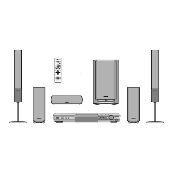
DVD Home Theater Sound System
SA-HT845E
SA-HT845EG
Colour
(S).......................Silver Type
lFM tuner section
Frequency Range:
Sensitivity:
S/N 26dB
Antenna Terminal:
lAM tuner section (AM/MW)
Frequency Range:
AM Sensitivity S/N 20dB at
999kHz:
Phone Jack:
Terminal:
lDisc section
Discs played [8 cm or 12 cm]:
(1) DVD-RAM (DVD-VR compatible, JPEG, MPEG4, DivX
formatted discs)
(2) DVD-Audio
(3) DVD-Video
(4) DVD-DivX
(5) DVD-R, DVD-RW (DVD-Video compatible, DivX)
+R, +RW (Video compatible)
(6) CD-Audio (CD-DA)
(7) Video CD
(8) SVCD (Conforming to IEC62107)
© 2005 Panasonic AVC Networks Singapore Pte.
Ltd. All rights reserved. Unauthorized copying and
distribution is a violation of law.
ORDER NO.MD0506227C2
87.5-108.0MHz
(50kHz in step)
1.5µV (IHF)
1.2µV
75Ω (non balance)
522-1629kHz (9kHz in step)
560µV/m
Stereo 3.5mm jack
Advertisement
Table of Contents

Related Manuals for Panasonic SA-HT845E


Summary of Contents for Panasonic SA-HT845E
- Page 1 50 W/ Channel (4Ω) (8) SVCD (Conforming to IEC62107) At 100Hz and total harmonic of 1% lSubwoofer: 160 W/ Channel (4Ω) © 2005 Panasonic AVC Networks Singapore Pte. Ltd. All rights reserved. Unauthorized copying and distribution is a violation of law.
- Page 2 (sub sampling is 4:2:2 or 4:2:0) Terminal S terminal (1 system) (12) MPEG4 Scart jack (1 system) lData recorded with Panasonic SC multi cameras or DVD Component video output: video recorders NTSC: 525(480)p/525(480)i: Conforming to SD VIDEO specifications (ASF PAL: 625(576)p/625(576)i: standard)/MPEG4 (Simple Profile) video system/G.726 audio...
-
Page 3: Table Of Contents
SA-HT845E / SA-HT845EG CONTENTS Page Page 1 Use of Active Subwoofer 11.7. Disassembling the DVD mechanism Unit 1.1. Checking Player when Active Subwoofer is not used 11.8. Disassembling the DVD Module P.C.B. 2 Safety Precautions 11.9. Disassembling the Rear panel 2.1. - Page 4 SA-HT845E / SA-HT845EG 16.2. Important points in adjustment 22 Schematic Diagram 16.3. Storing and Handling Test Discs 23 Printed Circuit Board Diagram 16.4. Optical adjustment 24 Wiring Connection Diagram 17 Abbreviations 25 Illustration of IC 痴, Transistors and Diodes 18 Voltage Chart 26 Terminal Function of ICs 18.1.
-
Page 5: Use Of Active Subwoofer
SA-HT845E / SA-HT845EG 1 Use of Active Subwoofer 1.1. Checking Player when Active Subwoofer is not used 1. This unit uses the active subwoofer to supply the power of the component, and the active subwoofer should be connected to the component to check operational conditions of the component. -
Page 6: Safety Precautions
SA-HT845E / SA-HT845EG 2 Safety Precautions 2.1. GENERAL GUIDELINES 1. When servicing, observe the original lead dress. If a short circuit is found, replace all parts which have been overheated or damaged by the short circuit. 2. After servicing, see to it that all the protective devices such as insulation barriers, insulation papers shields are properly installed. -
Page 7: Before Repair And Adjustment (Using Active Subwoofer)
SA-HT845E / SA-HT845EG Caution Be sure no power is applied to the chassis or circuit, and observe all other safety precautions. 8. Minimize bodily motions when handling unpackaged replacement ES devices. (Otherwise harmless motion such as the brushing together of your clothes fabric or the lifting of your foot from a carpeted floor can generate static electricity (ESD) sufficient to damage an ES device). -
Page 8: Precaution Of Laser Diode
SA-HT845E / SA-HT845EG 6 Precaution of Laser Diode 7 About Lead Free Solder (PbF) Distinction of PbF PCB: PCBs (manufactured) using lead free solder will have a PbF stamp on the PCB. Caution: · Pb free solder has a higher melting point than standard solder; Typically the melting point is 50 - 70°F (30 - 40°C) higher. -
Page 9: General Description
SA-HT845E / SA-HT845EG 8 General Description 8.1. Operating instructions AV SYSTEM /AV SYSTEM TUNER/BAND, TV/AV TUNER/BAND DVD/CD TV/AV DVD/CD NUMBERED BUTTONS VOLUME -/-- VOLUME CANCEL S 10 CANCEL SKIP SLOW/SEARCH (SLOW/SEARCH) (SKIP) (PLAY) (STOP) (PAUSE) TOP MENU MENU TOP MENU... -
Page 10: Disc Information
Recorded with devices using Version 1.1 of the Video Recording Format (a unified video recording standard), such as DVD video recorders, DVD video cameras, personal computers, etc. Recorded with Panasonic SD multi cameras or DVD video recorders using the DCF (Design rule for Camera JPEG File system) Standard Version 1.0. -
Page 11: About Highmat
SA-HT845E / SA-HT845EG 8.3. About HighMAT 8.3.1. What’s HighMAT? Consumers worldwide are using PCs to create their own collections of music, photos and even video by burning them onto CDs. But how these collections can be experienced across different devices can be confusing to navigate, time consuming to access for a DVD player, and be incomplete in terms of music information available to the customer. - Page 12 SA-HT845E / SA-HT845EG 8.3.2. Why take advantage of HighMAT? A Problem Defined:Today, when consumers create their own digital audio, video or photo collections on CD-R or other physical formats, there are numerous, inconsistent ways that devices read the data. For the consumer, the playback experience can be...
- Page 13 SA-HT845E / SA-HT845EG Conventional HighMAT Even though DVD player is CD-R/RW compatible, the inconsistent ways HighMAT compatible products play content back with consistent that various DVD players can read the music or photos files often leads interface. This includes products which are JPEG compatible products to a confusing and inconsistant playback experince.
- Page 14 SA-HT845E / SA-HT845EG HighMAT is now available for CD Burning and in Leading DVD Players HighMAT is a new technology that is now available in leading software and consumer electronic devices to dramatically improve the digital media experience when you create homemade CDs HighMAT delivers a simple, standardized way for PC software and consumer electronics devices to talk to each other and work better together.
- Page 15 SA-HT845E / SA-HT845EG When you create your homemade CDs with software that supports HighMAT CD burning, and then play them back on a DVD player that supports HighMAT, you get better, easier navigation. You get folders you can access with a single click of your DVD player´s remote control.
-
Page 16: Accessories
SA-HT845E / SA-HT845EG 9 Accessories Remote control AC cord System cable AM loop antenna FM indoor antenna Speaker label Video Cable Speaker cables... -
Page 17: Handling Precautions For Optical Pickup Unit
SA-HT845E / SA-HT845EG 10 Handling Precautions for Optical Pickup Unit The laser diode in the optical pickup unit may break down due to static electricity of clothes or human body. Special care must be taken avoid to electrostatic breakdown when servicing and handling the laser diode. - Page 18 SA-HT845E / SA-HT845EG 10.3.2. Human body grounding 1. Use the anti-static wrist strap to discharge the static electricity form your body.
-
Page 19: Disassembly And Main Component Replacement Procedure
SA-HT845E / SA-HT845EG 11 Disassembly and Main Component Replacement Procedure “ATTENTION SERVICER” Some chassis components may have sharp edges. Be careful when disassembling and servicing. 1. This section describes procedures for checking the operation of the major printed circuit boards and replacing the main components. -
Page 20: Main Components And P.c.b. Locations
SA-HT845E / SA-HT845EG 11.2. Main Components and P.C.B. Locations. -
Page 21: Disassembling The Top Cabinet
SA-HT845E / SA-HT845EG 11.3. Disassembling the Top Cabinet Step 1 Unscrew the screw. Step 2 Lift up and remove the top cabinet. 11.4. Disassembling the Lid assembly (When taking out disc manually) · Follow the (Step 1) - (Step 2) of Item 11.3. -
Page 22: Disassembling The Front Panel
SA-HT845E / SA-HT845EG 11.5. Disassembling the Front Panel · Follow the (Step 1) - (Step 2) of Item 11.3. · Follow the (Step 1) - (Step 3) of Item 11.4. Step 1 Remove the lid assembly from the tray section. -
Page 23: Disassembling The Dvd Module P.c.b
SA-HT845E / SA-HT845EG 11.9. Disassembling the Rear panel · Follow the (Step 1) - (Step 2) of Item 11.3. Step 1 Unscrew the screws. Step 2 Release the tabs. 11.10. Disassembling the Scart 11.8. Disassembling the DVD P.C.B. Module P.C.B. -
Page 24: Service Position
SA-HT845E / SA-HT845EG 11.12. Service Position 11.12.1. Servicing position of the DVD Module P.C.B. · Follow the (Step 1) - (Step 2) of Item 11.3. · Follow the (Step 1) - (Step 3) of Item 11.4. · Follow the (Step 1) - (Step 4) of Item 11.5. -
Page 25: Assembling And Disassembling The Mechanism Unit
SA-HT845E / SA-HT845EG 12 Assembling and 12.2. Traverse Unit disassembling the 1. Slide the lever (A) in the arrow direction (to the opposite side) till it stops. Mechanism Unit 2. Slide the lever (A) further by bending the tab at the right side of the lever A in the right direction. -
Page 26: Tray
SA-HT845E / SA-HT845EG 12.3. Tray 1. Slide the guide tray unit while pressing the stopper in the 5. Remove the drive arm concave phase from the tray slider arrow direction, and remove the guide tray unit. and tray. (Assembling the tray unit) 2. -
Page 27: Loading Section
SA-HT845E / SA-HT845EG 4. Remove the belt. 12.4. Loading section 5. Unlock the tab and remove the pulley. 6. Remove the relay gear. 1. Spread the tabs at the both sides and push out the drive arm shaft. 2. Hook the lock lever spring on the lock lever projection part temporarily. -
Page 28: Tray Loading P.c.b
SA-HT845E / SA-HT845EG part temporarily. 12.5. Tray Loading P.C.B. 1. Unscrew the screws 9. Pull the lever (B) in the bottom side to your side and remove the change lever. 10. Remove the drive rack, the sub rack and the drive gear. -
Page 29: Optical Pickup Unit
SA-HT845E / SA-HT845EG 12.6. Optical Pickup Unit 12.6.1. Procedure for Disassembling the Optical Pickup Unit 1. Spread the tabs to push in the pin. 2. Remove the pins. 4. Move the optical pickup unit in the arrow direction till it stops. - Page 30 SA-HT845E / SA-HT845EG 6. Remove the drive rack. 7. Unscrew the screw 8. Slide the shaft in the arrow direction. 11. Pull the shaft and the rubber out. 9. Lift the optical pickup unit with the shaft. 10. Remove the optical pickup unit.
-
Page 31: Traverse Motor And Spindle Motor
SA-HT845E / SA-HT845EG (Assembling the optical pickup unit) 1. Pass the intermediate FPC through the frame hole. 2. Remove the cover while lifting the inner gear. 2. Align the guide section of the optical pickup unit with the rail. 3. Install the shaft top to the holder. - Page 32 SA-HT845E / SA-HT845EG 5. Remove the solders. 6. Remove the screw lock as carefully as you can. 7. Unscrew the screws with torx screw driver (T6). 8. Remove the spindle motor.
-
Page 33: Optical Pick-Up Self-Diagnosis And Replacement Procedure
SA-HT845E / SA-HT845EG 13 Optical Pick-up Self-Diagnosis and Replacement Procedure 13.1. Optical Pickup Breakdown Diagnosis The optical pickup self-diagnosis function and tilt adjustment check function have been included in this unit. When repairing, use the following procedure for effective Self-diagnosis and tilt adjustment. Be sure to use the self-diagnosis function before replacing the optical pickup when "NO DISC"... -
Page 34: Service Mode Table
SA-HT845E / SA-HT845EG 13.2. Service Mode Table 1 The service modes can be activated by pressing various button combination on the player and remote control unit. Player buttons Remote control unit buttons Application Note STOP Error code display (Refer to the item, “13.3. - Page 35 SA-HT845E / SA-HT845EG Error Code Error Content Additional error explanation F890 Sending message when message is Sending message to AV task being sent to AV task F891 Message couldn’t be sent to AV task Begin sending message to AV task...
-
Page 36: Service Mode Table
SA-HT845E / SA-HT845EG 13.4. Service mode table 2 Pressing various button combinations on the player and remote control unit can activate the service modes. - Page 37 SA-HT845E / SA-HT845EG...
-
Page 38: Sales Demonstration Lock Function
SA-HT845E / SA-HT845EG 13.5. Sales demonstration lock function This function prevents discs from being lost when the unit is used for sales demonstrations by disabling the disc eject function. "LOCKED" is displayed on the unit, and ordinary operation is disabled. -
Page 39: Self-Diagnosis Function
SA-HT845E / SA-HT845EG 14 Self-Diagnosis Function 14.2. Memorized Error Codes 14.2.1. Activating Self-Diagnosis Function 14.1. Automatic Displayed Error and Displaying Method Codes 1. Turn on the power. 14.1.1. Automatic Display Function 2. Select DVD/CD function. With no DVD/CD inserted in the... -
Page 40: Service Precautions
SA-HT845E / SA-HT845EG 15 Service Precautions 15.1. Recovery after the DVD player is repaired · When FLASH ROM IC or DVD module P.C.B. is replaced, carry out the recovery processing to optimize the drive. Playback the recovery disk to process the recovery automatically. -
Page 41: Adjustment Procedure
SA-HT845E / SA-HT845EG 16 Adjustment Procedure 16.1. Service Tools and Equipment Application Name Number Tilt adjustment DVD test disc DVDT-S20 [SPG] TORX screw driver (T6) Available on sales route. (T6) or RFKZ0185 [SPG] Others Grease RFKXPG641 Harnal VFK1784 [SPG] Drysurf... - Page 42 SA-HT845E / SA-HT845EG 16.4. Optical adjustment 16.4.1. Optical pickup tilt adjustment Measurement point Adjustment point Mode Disc Tangential adjustment screw T01 (inner periphery) play DVDT-S20 [SPG] Tilt adjustment screw T30 (center periphery) play T43 (outer periphery) play Measuring equipment Adjustment value None (Main unit display for servicing is used.)
- Page 43 SA-HT845E / SA-HT845EG 17 Abbreviations INITIAL/LOGO ABBREVIATIONS INITIAL/LOGO ABBREVIATIONS A0~UP ADDRESS ERROR TORQUE CONTROL ACLK AUDIO CLOCK ERROR TORQUE CONTROL AD0~UP ADDRESS BUS REFERENCE ADATA AUDIO PES PACKET DATA ENCSEL ENCODER SELECT ADDRESS LATCH ENABLE ETMCLK EXTERNAL M CLOCK (81MHz/40.5MHz)
- Page 44 SA-HT845E / SA-HT845EG INITIAL/LOGO ABBREVIATIONS INITIAL/LOGO ABBREVIATIONS READ ENABLE VBLANK V BLANKING RFENV RF ENVELOPE COLLECTOR POWER SUPPLY RF PHASE DIFFERENCE OUTPUT VOLTAGE (CD-ROM) REGISTER SELECT VCDCONT VIDEO CD CONTROL (TRACKING RSEL RF POLARITY SELECT BALANCE) RESET DRAIN POWER SUPPLY VOLTAGE...
- Page 45 SA-HT845E / SA-HT845EG 18 Voltage Chart 18.1. DVD Module P.C.B. IC8001 Re f No. MODE CD P LAY IC8001 Re f No. MODE CD P LAY Re f No. IC8001 MODE CD P LAY IC8001 Re f No. MODE CD P LAY IC8001 Re f No.
- Page 46 SA-HT845E / SA-HT845EG 18.2. Main P.C.B. IC2006 Re f No. MODE CD P LAY S TANDBY Re f No. IC2009 IC2010 MODE CD P LAY -6.8 S TANDBY IC2011 Re f No. MODE CD P LAY S TANDBY IC2011 Re f No.
- Page 47 SA-HT845E / SA-HT845EG Q2201 Q2301 Q2302 Re f No. MODE CD P LAY -4.6 S TANDBY Re f No. Q2306 Q2500 Q2600 MODE CD P LAY S TANDBY Q2601 Q2604 Q2605 Q2607 Re f No. MODE CD P LAY -0.7...
- Page 48 SA-HT845E / SA-HT845EG 19 Wave Form Chart WF No. IC2006-2 (PLAY) WF No. IC2006-4 (PLAY) WF No. IC2006-6 (PLAY) WF No. IC2006-8 (PLAY) 0.6Vp-p(20usec/div) 1.1Vp-p(20usec/div) 1.1Vp-p(20usec/div) 0.5Vp-p(20usec/div) WF No. IC2006-9 (PLAY) WF No. IC2006-11 (PLAY) WF No. IC2006-12 (PLAY) WF No. IC2006-13 (PLAY) 1.0Vp-p(20usec/div)
- Page 49 SA-HT845E / SA-HT845EG 20 Schematic Diagram Notes · This schematic diagram may be modified at any time Caution! with the development of new technology. IC and LSI are sensitive to static electricity. Notes: Secondary trouble can be prevented by taking care during S901: Play detection switch.
- Page 50 SA-HT845E / SA-HT845EG...
- Page 51 SA-HT845E / SA-HT845EG 21 Block Diagram IC8001 IC8251 MN2DS0009AP C0GBG0000048 OPTICAL PICK UP UNIT DV3.2 LSI TRACKING COIL/FOCUS COIL/TRAVERSE/SPINDLE MOTOR DRIVE PHOTO DETECTOR VIN1 VOL4+ VIN2 TRAVERSE VIN4 HEAD MOTOR VIN3 LEVEL VOL4- SHIFT VIN8 BIAS1 VIN7 VHALF VIN6 TRV DRV...
- Page 52 SA-HT845E / SA-HT845EG IC8051 IC8001 IC8421 C3ABPG000145 MN2DS0009AP C0FBBK000050 64M SDRAM DV3.2 LSI AUDIO DAC OUTPUT AMP AND V OUT1 DVD MIX L LOW-PASS FILTER SRCK LRCK MEMORY MEMORY LRCK ADDRESS ADDRESS DATA2 V OUT2 DVD MIX R OUTPUT AMP AND...
- Page 53 SA-HT845E / SA-HT845EG TUNER PACK AM ANT FM ANT IC2006 C9ZB00000498 VIDEO DRIVE IC2009 MIXER C1AB00001486 IF AMP BIAS VIDEO BUFFER COIL COIL RF AMP 150K Q1101 (Q1201) Q2701 Y/PY/G BUFFER CY IN 13.5MHz CY OUT JK2001 MUTING Y(RED) MUTING...
- Page 54 SA-HT845E / SA-HT845EG IC2013 C0AABB000125 HEADPHONES AMP IC2011 C1BB00000845 (6)2 (58) (56) (54) 1(7) ASP(INPUT SELECT/DIGITAL SOUND PROCESSOR/ELECTRONIC VOLUME/TONE) (5)3 Q2102 Q2201 TMF L TMF RB TMF LB MUTING (TMFR) (TMF RA) (TMF LA) MUTING CONTROL (L OUT2) L OUT1...
- Page 55 SA-HT845E / SA-HT845EG SIGNAL LINES : MAIN SIGNAL LINE : AM SIGNAL LINE : DVD AUDIO SIGNAL LINE : FM SIGNAL LINE : AM OSC SIGNAL LINE : DVD VIDEO SIGNAL LINE : FM /AM SIGNAL LINE : CD-DA (AUDIO /VIDEO) SIGNAL LINE : FM OSC SIGNAL LINE ( ) Indicates the Pin No.
- Page 56 SA-HT845E / SA-HT845EG...
- Page 57 VIN8 GND(OEIC) CL8571 LB8531 ERJ2GE0R00X VIN7 VREF1 LB8530 J0JHC0000045 C8426 SUB2 CL8428 C8424 0.1 RX8533 SUB1 CL8427 R8532 2200 56X2 PIN(CD) VIN6 CL8431 SUBSEL VIN5 CL8432 GND(VRCD) R8533 0 C8428 0.1 C8530 C8533 C8532 CL8433 220P SA-HT845E/EG DVD MODULE CIRCUIT...
- Page 58 C8541 C8501 C8022 C8023 4700P 6V100 RX8403 100X2 TL8201 EXADR 20 C8528 1 R8002 R8541 C8503 C8504 RX8401 100X2 C8529 1 C8024 0.1 C8502 0.1 C8008 C8306 0.1 C8203 0.1 C8505 0.1 C8512 C8511 CL8512 CL8511 SA-HT845E/EG DVD MODULE CIRCUIT...
- Page 59 IC8651 C8551 RFKWMH90B160 16M Flash Q8341 2SB1218ARL Amplifier R8342 33 UNIT CHECK FOR PAVCSG UNIT CHECK FOR PAVCSG K8005 0 K8010 0 R8341 CL8034 CL8005 CL8006 CL8032 C8602 0.015 K8001 0 K8006 0 CL8019 CL8007 CL8652 SA-HT845E/EG DVD MODULE CIRCUIT...
- Page 60 SA-HT845E / SA-HT845EG SCHEMATIC DIAGRAM-4 MAIN CIRCUIT :+B SIGNAL LINE :-B SIGNAL LINE :MAIN SIGNAL LINE :DVD(VIDEO) SIGNAL LINE :FM/AM SIGNAL LINE CN2004 VGND H2000 TRY OPEN PY/Y/G TRY OPEN TRY CLOSE C2206 50V4.7 VGND TRY CLOSE LINE R CB B...
- Page 61 SA-HT845E / SA-HT845EG SCHEMATIC DIAGRAM-5 MAIN CIRCUIT :+B SIGNAL LINE :-B SIGNAL LINE :MAIN SIGNAL LINE C2163 R2163 50V3.3 FRONTL C2263 R2263 50V3.3 FRONTR R2622 27K -7.5V C2506 0.01 C2617 50V10 R2619 R2620 2.2K 1.8K MUTE SUB R2184 R2615 220K...
- Page 62 SA-HT845E / SA-HT845EG SCHEMATIC DIAGRAM-6 MAIN CIRCUIT :+B SIGNAL LINE :-B SIGNAL LINE :DVD(VIDEO) SIGNAL LINE Q2803 IC2801 B1BCCG000023 D2806 D2805 L2801 C0DAAMH00010 Regulator B0ECKM000016 B0ECKM000016 G0A101ZA0028 Regulator R2813 C2811 C2806 D2801 0.01 R2823 R2822 8.3V820 B0JCPD000025 2.2K 2.2K R2815 4.7K...
- Page 63 SA-HT845E / SA-HT845EG SCHEMATIC DIAGRAM-7 MAIN CIRCUIT :+B SIGNAL LINE :MAIN SIGNAL LINE E2000 C2840 K4CZ01000027 R2050 220 DC DET CN2008 R2051 220 KEY2 RDS CLK KEY2 R2043 220 R2085 0 R2897 JOG A R2052 220 JOG A RDS DA...
- Page 64 SA-HT845E / SA-HT845EG SCHEMATIC DIAGRAM-8 FL CIRCUIT :+B SIGNAL LINE :MAIN SIGNAL LINE FL6000 A2BD00000132 R6051 C6005 50V22 POWER KEY1 R6050 S6011 R6012 EVQ21405R R6038 SELECTOR K6036 R6011 D6006 S6012 B0BC5R000009 EVQ21405R R6006 CN6008 L6003 J0JBC0000041 C6003 R6013 C6007 LED9V...
- Page 65 SA-HT845E / SA-HT845EG SCHEMATIC DIAGRAM-9 TRAY LOADING CIRCUIT IC904 C0GAG0000022 REFLECTIVE PHOTO SENSOR CS901 TRAY CW M+9V GND1 MAIN CIRCUIT VREF+ (H2000)on TRAY CCW SCHEMATIC DIAGRAM-4 TRY CLOSE TRY OPEN S901 PLAY C984 25V10 S902 OPEN SA-HT845E/EG TRAY LOADING CIRCUIT...
- Page 66 SA-HT845E / SA-HT845EG...
- Page 67 CL8051 CL8064 RX8019 RX8015 RX8014 CKC44 RX8011 C8057 CL8430 C8421 CL8434 C8427 C8422 CKA1 CL8435 CKA3 CKA4 CKF5 CKF3 CKF1 IC8421 CKA2 CKA7 C8424 C8428 CKF6 CKA5 CKF4 CKF2 CL8428 CKA6 CL8425 C8426 CL8427 CL8426 FP8251 SA-HT845E/EG DVD MODULE P.C.B.
- Page 68 SA-HT845E / SA-HT845EG A A A A MAIN P.C.B. (REPX0485E) C2803 R2885 C2807 R2884 L2026 R2891 C2805 L2027 R2890 C2042 L2022 R2878 C2044 R2886 R2879 C2814 R2883 L2025 R2882 R2889 R2880 C2808 C2040 W2326 C2027 R2881 W2201 C2022 C2026 R2092...
- Page 69 FL P.C.B (REPX0457C) D6010 D6000 K6037 R6020 R6010 H_BASS PROGRESSIVE INPUT SELECTOR POWER S6013 S6012 S6014 R6005 S6011 C6011 IC6000 W604 W601 FL6000 TRAY LOADING P.C.B ( REP3288A IC904 S902 CS901 OPEN SW S901 PLAY SW SA-HT845E/EG SCART/VOLUME/TRAY LOADING/FL P.C.B.
- Page 70 SA-HT845E / SA-HT845EG...
- Page 71 SA-HT845E / SA-HT845EG 24 Wiring Connection Diagram OPTICAL PICKUP FL P.C.B. (SOLDER SIDE) 2526 FP8531 DVD MODULE P.C.B. (SIDE:A) CN2009 CN2008 VOLUME PHONES CN6032 VR6000 JK6002 VOLUME P.C.B. (SOLDER SIDE) Z6000 MAIN P.C.B. (SOLDER SIDE) SENSOR SPINDLE MOTOR ASS'Y FP8251 TRAY LOADING P.C.B.
- Page 72 SA-HT845E / SA-HT845EG...
- Page 73 SA-HT845E / SA-HT845EG 25 Illustration of IC’s, Transistors and Diodes C0ABBB000230 (8p) C3ABPG000145 (54p) RFKWMH90B160 C0HBB0000044 (40p) C0AABB000125 C0FBBK000050 (16p) C1BB00001008 (16p) C2CBJG000672 (100p) C0CBCBD00018 (8p) C3EBEG000072 (8p) MN2DS0009AP (256p) C1BB00000979 (20p) C1BB00000845 (80p) C3EBGC000044 (8p) C9ZB00000498 (16p) No.1 No.1...
- Page 74 SA-HT845E / SA-HT845EG 26 Terminal Function of ICs 26.1. IC2018 (C2CBJG000672): Terminal Function Name System control HB_LVL Not used, open CMIX Not used, open Terminal Function SURR_FC1 Surround Freq. Limiter 1 Name SURR_FC2 Not used, open TRY_ Loading mechanism close SW ( L: SW...
- Page 75 SA-HT845E / SA-HT845EG 27 Parts Location and Replacement Parts List Notes: *Important safety notice: Components identified by mark have special characteristics important for safety. Furthermore, special parts which have purposes of fire-retardant (resistors), high-quality sound (capacitors), low-noise (resistors), etc. are used.
- Page 76 SA-HT845E / SA-HT845EG 27.1. Loading Mechanism, Traverse Unit & Cabinet 27.1.1. Loading Mechanism, Traverse Unit & Cabinet Parts Location...
- Page 77 SA-HT845E / SA-HT845EG...
- Page 78 SA-HT845E / SA-HT845EG 27.1.2. Traverse and Cabinet Parts List Ref. Part No. Part Name & Description Remarks CABINET AND CHASSIS J3CCBC000008 TUNER PACK REEX0426 10P FFC WIRE (PANEL) REEX0427 19P FFC WIRE (FL) REEX0429 50P FFC (MECHA) REEX0466 10P FFC WIRE (SCART)
- Page 79 SA-HT845E / SA-HT845EG 27.2. Component Parts List Ref. Part No. Part Name & Description Remarks Ref. Part No. Part Name & Description Remarks Q2105 B1GDCFGA0018 TRANSISTOR PRINTED CIRCUIT BOARDS Q2200 B1GFGCAA0001 TRANSISTOR Q2201 B1GDCFGA0018 TRANSISTOR REP3908A DVD MODULE P.C.B Q2301...
- Page 80 SA-HT845E / SA-HT845EG Ref. Part No. Part Name & Description Remarks Ref. Part No. Part Name & Description Remarks D2824 B0BC7R500001 DIODE CS901 K1KA07B00027 7P CONNECTOR D2825 B0EAKM000117 DIODE CN1001 K1MN19B00026 19P CONNECTOR D2826 B0EAKM000117 DIODE CN2002 K1KA10AA0031 10P CONNECTOR...
- Page 81 SA-HT845E / SA-HT845EG Ref. Part No. Part Name & Description Remarks Ref. Part No. Part Name & Description Remarks JK2000 K1FB125B0097 JK SYSTEM CONNECTOR W6003 ERJ6GEY0R00V CHIP RESISTOR JK2001 K2HZ929B0001 JK COMBO W6005 ERJ6GEY0R00V CHIP RESISTOR JK6002 K2HC103A0024 JK SMALL SIGN...
- Page 82 SA-HT845E / SA-HT845EG Ref. Part No. Part Name & Description Remarks Ref. Part No. Part Name & Description Remarks R2034 ERJ3GEYJ221V 220 1/16W R2146 ERJ3GEYJ333V 33K 1/16W R2035 ERJ3GEYJ221V 220 1/16W R2147 ERJ3GEYJ220V 22 1/16W R2036 ERJ3GEYJ102V 1K 1/16W R2148...
- Page 83 SA-HT845E / SA-HT845EG Ref. Part No. Part Name & Description Remarks Ref. Part No. Part Name & Description Remarks R2267 ERJ3GEYJ563V 56K 1/16W R2625 ERJ3GEYJ223V 22K 1/16W R2268 ERJ3GEYJ273V 27K 1/16W R2627 ERJ3GEYJ104V 100K 1/16W R2269 ERJ3GEYJ562V 5.6K 1/16W R2629...
- Page 84 SA-HT845E / SA-HT845EG Ref. Part No. Part Name & Description Remarks Ref. Part No. Part Name & Description Remarks R2837 ERJ3GEYJ561V 560 1/16W R8011 ERJ2GEJ220X 22 2W R2838 ERJ3GEYJ272V 2.7K 1/16W R8012 ERJ2GEJ220X 22 2W R2839 ERJ3GEYJ821V 820 1/16W R8013...
- Page 85 SA-HT845E / SA-HT845EG Ref. Part No. Part Name & Description Remarks Ref. Part No. Part Name & Description Remarks C2029 ECJ1VB1A105K 1 10V RX8001 D1H410320002 CHIP RESISTOR C2030 ECJ1VB1A105K 1 10V RX8011 D1H88204A024 CHIP RESISTOR C2031 ECJ1VB1A105K 1 10V RX8012...
- Page 86 SA-HT845E / SA-HT845EG Ref. Part No. Part Name & Description Remarks Ref. Part No. Part Name & Description Remarks C2222 ECJ1VC1H391K 390P 50V C2613 ECJ1VB1E103K 0.01 25V C2223 ECEA1HKA100I 10 50V C2615 ECJ1VB1H562K 5600P 50V C2224 ECJ1VC1H101K 100P 50V C2616...
- Page 87 SA-HT845E / SA-HT845EG Ref. Part No. Part Name & Description Remarks Ref. Part No. Part Name & Description Remarks C2857 ECJ1VB1A225K 2.2 10V C8262 ECJ0EF1C104Z 0.1 16V C2858 ECJ1VB1A225K 2.2 10V C8301 F2G0J221A031 220P 6.3V C2859 ECJ1VB1H103K 0.01 50V C8302 F2G0J330A031 33P 6.3V...
- Page 88 SA-HT845E / SA-HT845EG 27.3. Packing Materials & Accessories Parts List Ref. Part No. Part Name & Description Remarks Ref. Part No. Part Name & Description Remarks K2CQ2CA00002 AC CORD PACKING MATERIALS RQT7975-D O/I BOOK (Ge/It/Fr) [M]EG RQT7976-1H O/I BOOK (Du/Da/Sw)
- Page 89 SA-HT845E / SA-HT845EG 27.4. Packaging...
Need help?
Do you have a question about the SA-HT845E and is the answer not in the manual?
Questions and answers