Table of Contents
Advertisement
file:///C|/Documents and Settings/lopez/Pulpit/s/PANASONIC SA-HT870E_EG_EB/ALL/SVC/s0000000000.html
Service Manual
TOP NEXT
ORDER NO.MD0403138C2
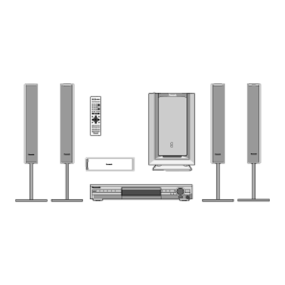
DVD Home Theater Sound System
SA-HT870E
SA-HT870EB
SA-HT870EG
Colour
(S).......................Silver Type
file:///C|/Documents and Settings/lopez/Pulpit/s/PANASONIC SA-HT870E_EG_EB/ALL/SVC/s0000000000.html (1 of 4)08-08-29 18:01:32
Specifications
• General
Power Source:
For (E, EG) areas:
AC 230 V, 50 Hz
For (EB) area:
AC 230-240 V, 50 Hz
Power consumption:
25 W
Dimensions (W× H× D):
430× 68× 359.2 mm
Mass:
3.2 kg
• Amplifier section
RMS Output Power: Dolby Digital Mode
• Total RMS Dolby Digital
1000 W
mode Power:
At 1kHz and total harmonic of 10%
• Front:
170 W/ Channel (6Ω )
• Center:
260 W/ Channel (4Ω )
• Surround:
70 W/ Channel (4Ω )
At 100Hz and total harmonic of 10%
• Active subwoofers:
260 W/ Channel (4Ω )
Advertisement
Table of Contents

Related Manuals for Panasonic SA-HT870


Summarization of Contents
Service Manual
Specifications
Provides detailed technical specifications for the DVD Home Theater Sound System.
1 Use of Active Subwoofer
1.1 Checking Player when Active Subwoofer is not used
Describes how to check the player when the active subwoofer is not in use.
2 Safety Precautions
2.1 GENERAL GUIDELINES
Outlines general guidelines and precautions to be followed for safety.
2.1.1 LEAKAGE CURRENT COLD CHECK
Details the procedure for performing a cold leakage current check.
2.1.2 LEAKAGE CURRENT HOT CHECK
Details the procedure for performing a hot leakage current check.
3 Prevention of Electro Static Discharge (ESD) to Electrostatically Sensitive (ES) Devices
Caution
Cautionary advice regarding handling components and power status during ESD prevention.
6 Precaution of Laser Diode
CAUTION: THIS PRODUCT UTILIZES A LASER.
Warns about the presence of a laser and potential hazards from controls or procedures.
7 About Lead Free Solder (PbF)
Caution:
Provides cautions regarding the handling and properties of lead-free solder.
8 General Description
8.1 Operating instructions
Describes how to operate the unit.
8.2 Disc information
Provides information about the types of discs the unit can play.
9 Accessories
Accessories Included
Lists all included accessories such as remote control, cables, and antennas.
10 Caution for AC Main Lead
IMPORTANT SAFETY NOTICE
Highlights critical safety notices regarding AC main lead and wiring.
11 Handling Precautions for Optical Pickup Unit
11.1 Cautions to Be Taken in Handling the Optical Pickup Unit
Details cautions for handling the optical pickup unit to prevent damage.
11.2 Cautions to Be Taken When Replacing the Optical Pickup
Outlines cautions to be observed when replacing the optical pickup.
11.3 Grounding for electrostatic breakdown prevention
Explains grounding procedures to prevent electrostatic breakdown.
12 DISASSEMBLING THE CASING AND CHECKING P.C.B.S
12.1 Disassembly Procedure
Provides the step-by-step procedure for disassembling the unit.
12.2 Casing Parts and P.C.B. Positions
Shows the locations of casing parts and PCBs within the unit.
12.11 Service Position
Shows the service positions for accessing internal components.
13 ASSEMBLING AND DISASSEMBLING THE MECHANISM UNIT
13.1 Disassembly Procedure
Provides the procedure for disassembling the mechanism unit.
13.6 Optical Pickup Unit
Details handling and replacement procedures for the optical pickup unit.
14 DVD-Optical Pick-up Self-Diagnosis and Replacement Procedure
14.1 Optical Pickup Breakdown Diagnosis
Guides on diagnosing optical pickup breakdowns.
14.2 Service Mode Table 1
Lists service modes activated by button combinations on the player.
14.3 DVD Self Diagnostic Function-Error Code
Provides a list of DVD self-diagnostic error codes and their meanings.
14.4 Last Error Code saved during NO PLAY
Details error codes saved when playback fails.
14.5 Service mode table 2
Provides a second table of service modes and their activation.
14.6 Sales demonstration lock function
Explains the function to lock the unit for sales demonstrations.
14.7 Handling After Completing Repairs
Outlines procedures to follow after completing repairs.
15 Self-Diagnosis Function
15.1 Automatic Displayed Error Codes
Details how error codes are automatically displayed.
15.2 Memorized Error Codes
Explains how to access and manage memorized error codes.
16 Service Precautions
16.1 Recovery after the DVD player is repaired
Describes the recovery process after repairs, including using a recovery disc.
16.2 Firmware version-up of the DVD player
Explains how to update the player's firmware using a recovery disc.
17 Adjustment Procedure
17.1 Service Tools and Equipment
Lists the necessary service tools and equipment for adjustments.
17.2 Important points in adjustment
Highlights crucial points to consider before and during adjustments.
17.3 Storing and Handling Test Discs
Provides guidelines for storing and handling test discs used for adjustment.
17.4 Optical adjustment
Details the procedure for optical adjustments.
19 Voltage Chart
19.1 DVD Module P.C.B.
Presents voltage values for the DVD Module PCB.
19.2 Main P.C.B.
Presents voltage values for the Main PCB.
19.3 Tray Loading P.C.B.
Presents voltage values for the Tray Loading PCB.
19.4 Scart P.C.B.
Presents voltage values for the Scart PCB.
19.5 FL P.C.B.
Presents voltage values for the FL PCB.
20 Schematic Diagram Notes
Notes:
Provides important notes and explanations for understanding the schematic diagrams.
26 Terminal Function of ICs
26.1 IC2018 (C2CBJG000466): System control
Details the terminal functions and operations of IC2018, the system control IC.
27 Parts Location and Replacement Parts List
Notes:
Contains important notes regarding safety, units, markings, and language references.
27.1 Loading Mechanism, Traverse Unit & Cabinet
Lists parts for the loading mechanism, traverse unit, and cabinet.
27.1.1 Loading Mechanism, Traverse Unit & Cabinet Parts Location
Shows the location of parts for the loading mechanism, traverse unit, and cabinet.
27.1.2 Traverse and Cabinet Parts List
Lists the part numbers for traverse and cabinet components.
27.2 Component Parts List
Lists all integrated circuits, transistors, diodes, resistors, etc., with part numbers.
27.3 Packing Materials & Accessories Parts List
Lists packing materials and accessories included with the unit.
27.4 Packaging
Provides details about the packaging of the unit.
Need help?
Do you have a question about the SA-HT870 and is the answer not in the manual?
Questions and answers