Table of Contents
Advertisement
Advertisement
Table of Contents

Related Manuals for Midea MSXTBU-09HRFN8-QRD6GW


Summary of Contents for Midea MSXTBU-09HRFN8-QRD6GW
- Page 1 TM_XT(GA)_R32_3D INV_EU_NA_2308 XT R32 3D INVERTER CONTROL TECHNICAL MANUAL...
-
Page 2: Table Of Contents
Table of Contents Page Specifications ...................... 3 Model Reference ....................... 4 General Specifications ....................5 Dimensional Drawings ....................7 Centre of gravity ....................... 10 Electrical Wiring Diagrams ..................11 Refrigerant Cycle Diagrams ..................13 Capacity Tables ......................14 Noise Criterion Curves ....................23 Electrical Characteristics .................... -
Page 3: Specifications
Specifications Contents Model Reference ....................4 General Specifications ................... 5 Dimensional Drawings ..................7 Centre of gravity ....................10 Electrical Wiring Diagrams ..................11 Refrigerant Cycle Diagrams .................. 13 Capacity Tables ....................... 14 Noise Criterion Curves ................... 23 Electrical Characteristics ..................25... -
Page 4: Model Reference
1. Model Reference Refer to the following table to determine the specific indoor and outdoor unit model number of your purchased equipment. Indoor Unit Model Outdoor Unit Model Capacity (Btu/h) Power Supply MSXTBU-09HRFN8-QRD6GW MOX230-09HFN8-QRD6GW 1Phase, 220-240V~, MSXTBU-12HRFN8-QRD6GW MOX230-12HFN8-QRD6GW 50Hz MSXTBU-18HRFN8-QRD0GW MOX301-18HFN8-QRD0GW ... -
Page 5: General Specifications
2. General Specifications MSXTBU-09HRFN8- MSXTBU-12HRFN8- MSXTBU-18HRFN8- Model QRD6GW QRD6GW QRD0GW Power supply V- Ph-Hz 220-240-1-50 220-240-1-50 220-240-1-50 Rated Power Input 2200 2200 2500 Rated Current 10.5 10.5 Model KSN98D64UFZ3 KSN98D64UFZ3 KSN140D21UFZ Type ROTARY ROTARY ROTARY Brand GMCC GMCC GMCC Capacity 1930/3100 1930/3100 4385... - Page 6 Number of rows Tube pitch(a)x row 21x22 21x22 21x22 pitch(b) Fin spacing Fin type (code) Hydrophilic aluminum Hydrophilic aluminum Hydrophilic aluminum Outdoor coil Tube outside dia.and Φ7,Inner groove tube Φ7,Inner groove tube Φ7,Inner groove tube type Coil length x height x 745*504*22 745*504*22 860*504*44...
-
Page 7: Dimensional Drawings
3. Dimensional Drawings Indoor Unit Capacity(Btu/h) W(mm/inch) D(mm/inch) H(mm/inch) 9k/12k/18k 920/36.22 211/8.31 321/12.64 Page 7 ... - Page 8 Outdoor Unit 9k/12k Page 8 ...
- Page 9 Page 9 ...
-
Page 10: Centre Of Gravity
4. Centre of gravity 9k/12k Page 10 ... -
Page 11: Electrical Wiring Diagrams
5. Electrical Wiring Diagrams Indoor unit Abbreviation Paraphrase Yellow-Green Conductor Positive and Negative Ion Generator Capacitor PLASMA Electronic Dust Collector LIVE NEUTRAL Indoor Room Temperature Coil Temperature of Indoor Heat Exchanger 9k/12k/18K Optiona l Optiona l Applicable to INDOOR WIRING DIAGRAM AC motor only 16022000036509 5(3or2) - Page 12 Outdoor Unit Abbreviation Paraphrase 4-WAY Gas Valve Assembly/4-WAY VALVE AC-FAN Alternating Current FAN DC-FAN Direct Current FAN COMP Compressor 9k/12k/18k Page 12 ...
-
Page 13: Refrigerant Cycle Diagrams
6. Refrigerant Cycle Diagrams Heat pump Pipe Size (Diameter:ø) Piping length (m/ft) Elevation (m/ft) mm(inch) Additional Capacity(Btu/h) Refrigerant Liquid Rated Max. Rated Max. 9k/12k 9.52(3/8) 6.35(1/4) 5/16.4 25/82 10/32.8 12g/m (0.13oz/ft) 12.7(1/2) 6.35(1/4) 5/16.4 30/98.4 20/65.6 Page 13 ... -
Page 14: Capacity Tables
7. Capacity Tables Cooling ID WB 16.0 18.0 19.0 22.0 INDOOR (℃) OUTDOOR AIRFLOW DB(℃) ID DB (CMH) 23.0 25.0 27.0 30.0 23.0 25.0 27.0 30.0 23.0 25.0 27.0 30.0 23.0 25.0 27.0 30.0 (℃) 2.75 2.73 2.76 2.79 2.89 2.95 2.95 2.98... - Page 15 2.83 2.86 2.89 2.92 2.95 2.95 2.95 2.98 3.03 3.03 3.03 3.06 3.23 3.23 3.23 3.23 0.79 0.91 0.98 1.00 0.61 0.72 0.84 0.96 0.52 0.64 0.75 0.86 0.33 0.42 0.53 0.64 0.41 0.41 0.41 0.41 0.41 0.41 0.41 0.41 0.41 0.41 0.41...
- Page 16 ID WB 16.0 18.0 19.0 22.0 INDOOR (℃) OUTDOOR AIRFLOW DB(℃) ID DB (CMH) 23.0 25.0 27.0 30.0 23.0 25.0 27.0 30.0 23.0 25.0 27.0 30.0 23.0 25.0 27.0 30.0 (℃) 3.71 3.72 3.72 3.75 3.90 3.96 3.96 3.96 4.00 4.00 4.00 4.00...
- Page 17 3.84 3.87 3.90 3.93 4.02 4.02 4.02 4.05 4.12 4.12 4.12 4.15 4.40 4.40 4.40 4.40 0.79 0.92 1.00 1.00 0.61 0.72 0.84 0.98 0.52 0.64 0.75 0.86 0.33 0.43 0.53 0.64 0.62 0.62 0.62 0.62 0.62 0.62 0.62 0.62 0.62 0.62 0.62...
- Page 18 ID WB 16.0 18.0 19.0 22.0 INDOOR (℃) OUTDOOR AIRFLOW DB(℃) ID DB (CMH) 23.0 25.0 27.0 30.0 23.0 25.0 27.0 30.0 23.0 25.0 27.0 30.0 23.0 25.0 27.0 30.0 (℃) 5.50 5.50 5.50 5.50 5.78 5.90 5.90 5.90 5.93 5.93 5.93 5.93...
- Page 19 5.74 5.74 5.80 5.86 6.05 6.05 6.05 6.05 6.20 6.20 6.20 6.20 6.57 6.57 6.57 6.57 0.70 0.79 1.00 1.00 0.56 0.65 0.73 0.98 0.50 0.58 0.66 0.74 0.35 0.42 0.49 0.57 1.11 1.11 1.11 1.11 1.10 1.10 1.10 1.10 1.11 1.11 1.11...
- Page 20 Heating [SI_Unit] HEATING PERFORMANCE AT INDOOR DRY BULB TEMPERATURE TC:TOTAL CAPACITY IN KILOWATTS (KW) PI:TOTAL POWER IN KILOWATTS (KW) INDOOR OUTDOOR AIRFLOW (CMH) Indoor Conditions (DB °C ) Indoor Conditions (DB °C ) DB(°C) 16.0 20.0 22.0 24.0 16.0 20.0 22.0 24.0 -25.0...
- Page 21 [SI_Unit] HEATING PERFORMANCE AT INDOOR DRY BULB TEMPERATURE TC:TOTAL CAPACITY IN KILOWATTS (KW) PI:TOTAL POWER IN KILOWATTS (KW) INDOOR OUTDOOR AIRFLOW (CMH) Indoor Conditions (DB °C ) Indoor Conditions (DB °C ) DB(°C) 16.0 20.0 22.0 24.0 16.0 20.0 22.0 24.0 -25.0 2.31...
- Page 22 [SI_Unit] HEATING PERFORMANCE AT INDOOR DRY BULB TEMPERATURE TC:TOTAL CAPACITY IN KILOWATTS (KW) PI:TOTAL POWER IN KILOWATTS (KW) INDOOR OUTDOOR AIRFLOW (CMH) Indoor Conditions (DB °C ) Indoor Conditions (DB °C ) DB(°C) 16.0 20.0 22.0 24.0 16.0 20.0 22.0 24.0 -15.0 4.33...
-
Page 23: Noise Criterion Curves
8. Noise Criterion Curves Indoor Unit 0.8m Microphone Notes: -Sound measured at 1.0m away from the center of the unit. -Data is valid at free field condition -Data is valid at nominal operation condition -Reference acoustic pressure OdB = 20µPa -Sound level will vary depending on a range of factors such as the construction -(acoustic absorption coefficient) of particular room in which the equipment is installed. - Page 24 Outdoor Unit Note: H= 0.5 × height of outdoor unit Notes: -Sound measured at 1.0m away from the center of the unit. -Data is valid at free field condition -Data is valid at nominal operation condition -Reference acoustic pressure OdB=20µPa -Sound level will vary depending on arrange off actors such as the construction (acoustic absorption coefficient) of particular room in which the equipment is installed.
-
Page 25: Electrical Characteristics
9. Electrical Characteristics Indoor Unit Power Supply Model Phase Voltage MSXTBU-09HRFN8-QRD6GW 220-240 0.063 MSXTBU-12HRFN8-QRD6GW 220-240 0.063 MSXTBU-18HRFN8-QRD0GW 220-240 0.063 Outdoor Unit Power Supply Compressor Model Phase Voltage MOX230-09HFN8-QRD6GW 220-240 6.75 11.4 4.65 0.89 MOX230-12HFN8-QRD6GW 220-240 6.75 11.4 4.65 0.89 MOX301-18HFN8-QRD0GW 220-240 10.4... -
Page 26: Product Features
Product Features Contents Operation Modes and Functions ................28 Display Function ..................28 Abbreviation ....................29 Safety Features ....................29 Fan Mode ....................29 Cooling Mode .....................29 Heating Mode(Heat Pump Units) ..............30 Auto Mode ....................32 Drying Mode ....................32 Forced Operation Function ................32 1.10 Timer Function ....................32 1.11 Sleep Function .....................33 1.12 Auto-Restart Function ..................33 1.13 Active Clean function ..................33... - Page 27 Contents 1.19 Breeze away function(Optional) ..............34 1.20 Wireless control(optional) ................34 1.21 Cascade Function(optional) ................34 Remote Controller Functions ................35 Infrared Wireless Remote Controller.............35...
-
Page 28: Operation Modes And Functions
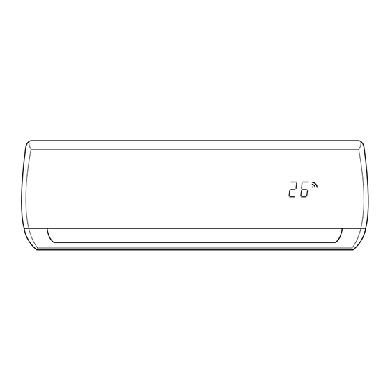
1. Operation Modes and Functions Display Function Unit display functions Display Function ECO function WiFi control (available on select units only) Temperature value Temperature Timer ON is set Activation of Fresh, Swing, Turbo, ECO, Breeze away, (3s) Cascade or Silence Timer OFF is set Cancellation of Fresh, Swing, Turbo, ECO, Breeze away, (3s) -
Page 29: Abbreviation
Abbreviation • If the unit is in heating mode, the indoor fan is regulated by the anti-cold wind function. Unit element abbreviations Sensor redundancy and automatic shutoff Abbreviation Element • If one temperature sensor malfunctions, the air conditioner continues operation and displays the Indoor room temperature corresponding error code, allowing for emergency use. -
Page 30: Heating Mode(Heat Pump Units)
1.5.4 Condenser Temperature Protection 3) If one of the following conditions is satisfied, not judge protective time. • Compressor running frequency(fr) is more than test frequency(TestFre). • Compressor running frequency is equal to test frequency, T4 is more than 15°C or T4 fault. •... - Page 31 1.6.3 Outdoor Fan Control: • Compressor running frequency(fr) is more than test frequency(TestFre). • The outdoor unit will be run at different fan speed • When compressor running frequency is equal to according to T4 and compressor running frequency. test frequency, T4 is more than 15°C or T4 fault. •...
-
Page 32: Auto Mode
1.6.5 Evaporator Temperature Protection room temperature exceeds 12°C. Forced Operation Function • Forced cooling mode: The compressor and outdoor fan continue to run(fixed at rated frequency), and the indoor fan runs at rated speed. After running for 30 minutes, the AC will switch to auto mode with a preset temperature of 24°C. -
Page 33: Sleep Function
on automatically when reaching the setting “on” time. minutes, the unit will turn off automatically and cancel Active Clean function. • The timer function will not change the AC current operation mode. Suppose AC is off now, it will not 1.14 Follow me(Optional) start up firstly after setting the “timer off”... -
Page 34: Electrical Energy Consumption Control Function(Optional)
ECO mode .The setting temperature and setting fan speed can be changed through remote controller signal. 1.18 Electrical energy consumption control function (Optional) Press the “Gear” button on remote controller to enter the energy efficient mode in a sequence of following: Turn off the unit or activate ECO, sleep, Super cool, 8°C Heating, Silence or self clean function will quit this function. -
Page 35: Remote Controller Functions
2. Remote Controller Functions Infrared Wireless Remote Controller- RG10X1(G2HS)/BGEF(Standard) Remote Controller Specifications Model RG10X1(G2HS)/BGEF Rated Voltage 3.0V (Dry batteries R03/LR03×2) Reaching Distance Environment Temperature Range -5°C~60°C(23°F~140°F) Buttons and Functions ON/OFF MODE Turns the unit on or off. Scrolls through operation modes as follows: AUTO COOL TEMP... - Page 36 Remote LCD Screen Indicators Active clean display Breeze away people(downward) Fresh feature display Breeze away people(upward) Sleep mode display Not applicable for this unit Follow me feature display Not applicable for this unit Wireless control feature display Not applicable for this unit Not applicable for this unit Low battery detection display (If flashes)
- Page 37 How To Use The Basic Functions Setting Temperature The operating temperature range for units is 16-30 C/60- F. You can increase or decrease the set temperature in F increments. AUTO Operation In AUTO mode, the unit will automatically select the COOL, FAN, HEAT or DRY mode based on the set temperature.
- Page 38 FAN Operation 1. Press the MODE button to select FAN mode. 2. Press the FAN button to select the fan speed in a range of Au-100%, in conjunction with Temp Temp button. 3. Press the ON/OFFbutton to start the unit. NOTE: You can’t set temperature in FAN mode.
- Page 39 How To Use The Advanced Functions • Under GEAR operation, the display on the remote controller will alternate between electrical energy SET Function consumption and set temperature. • Press the SET button to enter the function setting, Breeze Away Function( then press SET button or Temp or Temp button...
- Page 40 LED Display • Press this button to turn on and turn off the display on the indoor unit. • Keep pressing this button more than 5 seconds, the indoor unit will display the actual room temperature. Press more than 5 seconds again will revert back to display the setting temperature.
-
Page 41: Installation
Installation Contents Accessories ......................42 Installation Summary-Indoor unit ................ 43 Location selection ....................44 Indoor Unit Installation ..................45 Outdoor unit installation(Side Discharge Unit) ........... 49 Refrigerant Pipe Installation ................. 50 Vacuum Drying and Leakage Checking ..............52 Additional Refrigerant Charge ................53 Electrical and Gas Leak Checks ................ -
Page 42: Accessories
Accessories Name Shape Quantity Mounting plate Clip anchor 5~8(depending on models) Mounting plate fixing screw ST3.9 X 25 5~8(depending on models) Remote controller Mode ON/OFF Timer Follow Self TurboI clean Fixing screw for remote controller holder ST2.9 x Optional Parts Remote controller holder Dry battery AAA.LR03 Seal... -
Page 43: Installation Summary-Indoor Unit
1. Installation Summary-Indoor unit Installation Order 15cm (5.9in) 12cm 12cm (4.75in) (4.75in) 2.3m (90.55in) Attach Mounting Plate Select Installation Location Determine Wall Hole Position Drill Wall Hole Connect Piping Connect Wiring (not applicable for some locations in North America) Wrap Piping and Cable Prepare Drain Hose (not applicable for some locations in North America) STEP... -
Page 44: Location Selection
2. Location selection Unit location selection can refer to installation manual. DO NOT install the unit in the following locations: • Where oil drilling or fracking is taking place. • Coastal areas with high salt content in the air. • Areas with caustic gases in the air, such as near hot springs. -
Page 45: Indoor Unit Installation
3. Indoor Unit Installation Correct orientation of Mounting Plate Service space for indoor unit 15cm (5.9in) or more 12cm (4.75in) 12cm (4.75in) or more or more Indoor unit outline 410(16.1) 2.3m (90.55in) or more pipe hole pipe hole 65(2.5) 65(2.5) Attach mounting plate to wall 110(4.3) 50(1.9) - Page 46 Prepare refrigerant piping Be extremely careful not to dent or damage the piping while bending them away from the unit. Any dents in the The refrigerant piping is inside an insulating sleeve piping will affect the unit’s performance. attached to the back of the unit. You must prepare the piping before passing it through the hole in the wall.
- Page 47 Connect signal and power cable • Signal Cable: H07RN-F Table: Minimum Cross-Sectional Area able of Power and 3.6.1 Before performing electrical work, read Signal Cables these regulations Rated Current of Nominal Cross-Sectional 1. All wiring must comply with local and national electrical codes, and must be installed by a licensed electrician.
- Page 48 plastic panel on the back. NOTE: NOTE: • Drain hose must be on bottom Make sure that the drain hose is at the bottom of the • Choose the right cable size bundle. Putting the drain hose at the top of the bundle The size of the power supply cable, signal cable, fuse, and can cause the drain pan to overflow, which can lead to fire switch needed is determined by the maximum current...
-
Page 49: Outdoor Unit Installation(Side Discharge Unit)
4. Outdoor unit installation(Side Discharge Unit) Service space for outdoor unit 3. Connect drain hose and refrigerant piping (refer to Refrigerant Piping Connection section of this manual for instructions). 4. Keep pipe connection point exposed to perform the leak test (refer to Electrical Checks and Leak Checks section of this manual). -
Page 50: Refrigerant Pipe Installation
5. Refrigerant Pipe Installation deforming. Do not touch the fan with hands or other objects. Maximum length and drop height Do not lean it more than 45, and do not lay it sidelong. Ensure that the length of the refrigerant pipe, the number Make concrete foundation according to the specifications of bends, and the drop height between the indoor and of the outdoor units. - Page 51 Flare form Pipe • After flared the pipe, the opening part must be seal by end cover or adhesive tape to avoid duct or exog- enous impurity come into the pipe. 7. Drill holes if the pipes need to pass the wall. 8.
-
Page 52: Vacuum Drying And Leakage Checking
6. Vacuum Drying and Leakage water might penetrated into pipeline. Checking 3. Construction period is long, and rain water might penetrated into pipeline. Purpose of vacuum drying 4. Rain water might penetrate into pipeline during construction. • Eliminating moisture in system to prevent the phe- nomena of ice-blockage and copper oxidation. -
Page 53: Additional Refrigerant Charge
7. Additional Refrigerant Charge 8. Electrical and Gas Leak Checks • After the vacuum drying process is carried out, the additional refrigerant charge process need to be Electrical Safety Checks performed. • After installation, confirm that all electrical wiring is The outdoor unit is factory charged with refrigerant. -
Page 54: Test Operation
9. Test Operation 5. After the Test Run is successfully completed, and you confirm that all checks points in List of Checks to Perform have PASSED, do the following: Before test run: • Using remote control, return unit to normal operating Only perform test run after you have completed the temperature.
Need help?
Do you have a question about the MSXTBU-09HRFN8-QRD6GW and is the answer not in the manual?
Questions and answers