Table of Contents
Advertisement
Quick Links
H-3062.3F
Operating Manual
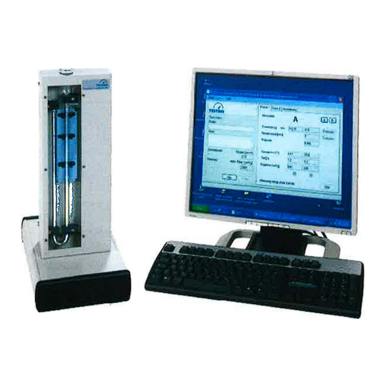
PC-Controlled Blaine Apparatus
with measuring cell acc. EN-Standard for determining the fineness
(PC optional)
Humboldt Mfg. Co.
U.S.A. Toll Free: 1.800.544.7220
875 Tollgate Raod
Voice: 1.708.468.6300
Elgin, Illinois 60123 U.S.A.
Fax: 1.708.456.0137
Email: hmc@humboldtmfg.com
1
Advertisement
Table of Contents

Subscribe to Our Youtube Channel
Related Manuals for Humboldt H-3062.3F


Summary of Contents for Humboldt H-3062.3F
- Page 1 H-3062.3F Operating Manual PC-Controlled Blaine Apparatus with measuring cell acc. EN-Standard for determining the fineness (PC optional) Humboldt Mfg. Co. U.S.A. Toll Free: 1.800.544.7220 875 Tollgate Raod Voice: 1.708.468.6300 Elgin, Illinois 60123 U.S.A. Fax: 1.708.456.0137 Email: hmc@humboldtmfg.com...
-
Page 2: Table Of Contents
Warning: It is expected that Users and Operators read and understand this entire Op erating Manual before putting the system into operation. Reading and understanding this entire Operating Manual is absolutely necessary before operating the system. Contents Page no.: General information ......................3 Manufacturer's designation .......................... -
Page 3: General Information
General information Manufacturer's designation Manufacturer's designation: please see the cover page of this Operating Manual Designation of the model itself: Please see the nameplate (rating plate) on the unit. It provides all the characteristics and the electrical rating data. Purpose for which this system has been designed This Operating Manual contains the information required for operation of the products described here, for the purpose for which they have been designed. -
Page 4: Conditions Under Which This System May Not Be Used
The Manufacturer cannot accept any responsibility for any damages that occur owing to false use of this apparatus. This operating manual contains safety instructions .that are to be observed in order to exclude any risk of fatalities, injuries, damage to the equipment or improper operation. Safety markings are as follows: Caution This warning refers to dangers that could cause material damage. -
Page 5: Safety Instructions
The Manufacturer guarantees trouble-free operation only if the User observes the in structions in this Operating Manual, and only if the User employs the Blaine Apparatus for the purpose for which it is intended. The Manufacturer cannot be held liable for damages that may occur if the Blaine Appa ratus is used for purposes for which it is not intended, or if the User does not observe the instructions and rules for operation as set forth in this Operating Manual. -
Page 6: Acceptance Of The Product And Transport
If there are any malfunctions or other trouble that could cause dangerous situations to arise in work with the Blaine Apparatus, these difficulties must be immediately corrected before working with the apparatus. Danger The mixing of cement with water causes the release of alkaline sub stances. -
Page 7: Transport
• Send a specialized fitter/installer to your plant, or • Ask that you return the system to us for repair. 1.6.2 Transport This system will be delivered in the appropriate cardboard boxes. In order to prevent transport damage, the remaining hollow spaces in the interior of the boxes will be filled with bulk material. -
Page 8: Instructions For Electrical Connection
Instructions for electrical connection Danger The electrical connections must be made by properly qualified electri cians. Before making the power connections, make sure that your power supply is in accordance with the required power and frequency ratings given in these instructions and on the equipment rating plate. The power plug must have a safety device (an overcurrent trip) that protects the system against overcurrent. -
Page 9: Technical Data
1- Opening to fill the manometer liquid 2- U- shaped tube 3- Measuring section with photoelectric barrier 4- Measuring cell with piston and sieve plates 5- socket Rear side: Power switch Connection as serial interface Technical data Power rating: 110-230 V / 50-60 Hz Measuring cell: 012.7 mm Volume of the measuring cell:... - Page 10 � Test � s· o" :::::, � � suck the liquid wlh syringe C'" <i>" insert the tube into the U-tube fill the liquid up to the mart '< � ..conned power line "O installation of the software "O switch on the device start the Software...
- Page 11 app. Constant calibration! select reference material fill the with reference material compress the reference material on top of the socket without piston start the calibration automatically calculation of the Constant emptying the eel test material known? manaQe the test material �...
-
Page 12: Filling The U-Shaped Tube
Filling the U-shaped tube Use the injection with hose, supplied by the Manufacturer, to pour the filling oil into the LI-shaped tube. Before filling the tube, make sure that it is clean and dry. Use the injection unit to remove liquid from the bottle in which it is delivered. Insert the end of the injector hose into the U-shaped tube. -
Page 13: Installation Of The Software
Installation of the software Note A PC with Windows XP, Vista, 7 is required to operate Blaine Appa ratus. The PC is not part of the scope of delivery. Insert the provided CD into the proper drive of the PC. Use Windows Explore to read the directory of the CD. -
Page 14: Advance Settings For Conducting The Test
Advance settings for conducting the test Selection of the interface Use the menu "Tools" to make the required settings for your serial interface (e.g. COM). Then click on the button "OK". interface .stledion ·I Serial port: [cOM20 Jlbbort Accept Setting the parameters for your specific apparatus To exactly perform the testing, it is necessary to select or to determine the required test parameters. -
Page 15: Determination Of The Measuring-Cell Data
4.2.1 Determination of the measuring-cell data Diameter Use a vernier calliper (slide gauge) to measure the diameter of the [e.g. measuring cell. Record this value. 12.65 mm] Bed height Place the sieve plate and two filter papers into the measuring cell and [e.g. -
Page 16: Output Format
After runs: deactivated Pre-stroke: The user can determine here whether the system will pull in air through the powder bed before the individual measurement begins. The pre-stroke will not result in calculation of the cycle time. 4.2.5 Output format At the end of testing, the User can save the test-result data in two different formats: *.txt Here, the data will be saved in Text Editor format. -
Page 17: The Pump Perfomance
4.2.6 The pump perfomance The aspiration of the manometer fluid can be determined or changed by the pump ca pacity. Starting time Specifies the startup behavior of the pump [0.01] Pumping power Can be set from 0% -100% (full power) [20] 0,01 I (s) -
Page 18: Management Of The Test Material
Management of the test material The User can enter several and various test material for purposes of comparative meas urements. To do this, open the menu "Tools - Manage of test material". lil: Blai11e 1.5 • Oeterm1tuition of fineness (Air perm Manage testmaterial �, Help... -
Page 19: Calibration Of The Apparatus
Calibration of the apparatus 4.4.1 General instructions The Blaine Apparatus Model 1.0297 is not calibrated before being de Note livered to the User. To determine the constant of the Blaine Apparatus, it is necessary to run 3 testing cycles with at least 3 different sample weights. The mean (average) value is then calculated. The determination of the apparatus constants takes place as described in EN 196-6. -
Page 20: Determination Of The Apparatus Constants
Name: Enter the reference name in this field. You can manage the calibra- tion substances by entering or removing these names. Density: Enter the density of the calibration substance. Specific surface: Enter the specific surface of the calibration substance. Apparatus con- The present constant for the calibration substance will be displayed. - Page 21 On the left side, the User can enter the name of the Tester, and can make a few notes. Then select the reference type: in other words, the calibration substance. Use the button "Next" to move to the right side of the test. &...
- Page 22 � l:°EJl!J � '·"''811!11111.5 • C.Jibmloii H8'I FIie Toole Teti 1To112 ITetl 3 Rodi TES<;?,JG � 2,517 Weight fllt 2,518 Import Comment: Reoldual apodng pm): Import Porollly : D.500 Reference T"""""""'1'CJ : 20,5 20,5 REF\ obc Thne (o): 2,65 F'tr8Dwllll)lfll/cm']: 55,55 Reoult: Spedlc llllfac•...
-
Page 23: Data Security
Data security Note To prevent complete loss of data by improper User actions or by failure of the PC, we recommend saving the apparatus settings that you have made in a backup file. Open the folder in which the installation files are located. Open the file Blaine.ini and save it under another name: for example, Blaine backup.ini. -
Page 24: Conducting The Tests
Conducting the tests The following example is given to describe the test procedure. During the production process, it is required to test sample type "XYZ" [A]. This sample type has already been stored in the database, and the following values are already known: Test material Density [g/cm... - Page 25 � - - - ---- � - --- o l _ e _ t _ es �� =· � ..,, Bl1lne1.5·Dehnnfnltio11of.flntnm-(Alrll'ffllubifi ty me'lftodl � ,.__ Tools Help TESt.;?,JG Test 1 Tee 2 Tell Examiner: 2.518 Import choose test material Repetitions for each sample r- .., , .
- Page 26 Finally, slowly retract the piston, without loosening the test material. Then place the measuring cell onto its support, and turn it to its proper position. ',-;- , Bl1lnt 1.J • �llllon � flMn-(AI, ptm1ublr11y mtlhod) Tool, � Test 1 Tcot2 TOJI 3 Te•4 Red Insert value or/ pmpooed resp.
- Page 27 After the measurement is finished, take the measuring cell from its support. Use the hand tamper to press the test material out from the bottom. Then repeat the measure ments a second and a third time, in the same manner as described above. Finally, the average (mean) of the results is calculated as final result.
-
Page 28: Maintenance And Cleaning
Maintenance and cleaning In case of special maintenance work (e.g., repairs, exchange of parts, and all other work that is not described in this Operating Manual), please get directly in touch with the man ufacturer. The Blaine Apparatus requires practically no maintenance. After long service, we rec ommend a thorough cleaning and refilling of the U-shaped tube with the required liquid. -
Page 29: Troubleshooting
Troubleshooting This section describes a number of simple problems tht can be easily solved during work. & Caution All maintenance, inspection, testing, and repair work on apparatus components or on the electrical system may be performed ONLY by sufficiently qualified personnel. PROBLEM CAUSE SOLUTION... -
Page 30: Shutting Down The System For Lengthy Periods
glass cone and cell Get in touch with the Supplier The measured The constant for the apparatus is Correctly determine the con- values are not cor- not correct. stant for the system. rect. The calibration substance does Choose the proper calibration not properly match the test mate- substance to correctly match rial. -
Page 31: After-Sales Service
1 O. After-sales service A great deal of care has been taken to ensure that this Operating Manual is correct. We cannot, however, guarantee that it is without mistakes or errors, or that all information contained herein will continue to remain valid in the event of technical changes. 10.1 Date of issue of this Operating Manual Issue no. - Page 32 EC Declaration of Conformity in accordance with the Machinery Directive 2006/42/EC Appendix II 1.A The authorised representative established in the community, Mr. Feuerherdt hereby declares that the following product Manufacturer: TESTING Bluhm & Feuerherdt GmbH Motzener Str. 26b 12277 Berlin Product designation: 1.0297/1.0297E Serial number:...
- Page 33 Record of Measurement and Testing DIN VOE 57 100 - DGUV Vorschrift 3 □ Acceptance testing Testing after a repair Model/ Type Article number Production number PC-controlled Blaine App. 1.0297/1.0297E 60-2016 Ratings Voltage Frequency Amperage Class of protection ---- 240V 110 - 50 Hz I ( VOE 0100)
- Page 34 Material Safety Data Sheet 1. IDENTIFICATION OF THE SUBSTANCE/PREPARATION AND COMPANY/UNDERTAKING Material Name : Shell Tellus S2 V 15 Uses : Hydraulic oil 001 D7747 Product Code : Manufacturer/Supplier : PT Shell Indonesia Talavera Office Park 22nd-27th Floor 22-26 JI. Letjen TB Simatupang Kav.
- Page 35 sheet as input to a risk assessment of local circumstances to help determine appropriate controls for safe handling, storage and disposal of this material. Avoid prolonged or repeated contact with skin. Avoid inhaling vapour and/or mists, When handling product Handling: in drums, safety footwear should be worn and proper handling equipment should be used.
- Page 36 11. TOXICOL OGICAL INFORMATION Basis for Information given is based on data on the components and the toxicology of similar products. Assessment : Expected to be of low toxicity: LD50 > 5000 mg/kg , Rat Aspiration into the lungs may cause chemical Acute Oral Toxicity : pneumonitis which can be fatal.
Need help?
Do you have a question about the H-3062.3F and is the answer not in the manual?
Questions and answers