Table of Contents
Advertisement
Quick Links
Advertisement
Table of Contents

Related Manuals for MHSC MAJESTIC LFP36 DESIGNER PENINSULA


Summary of Contents for MHSC MAJESTIC LFP36 DESIGNER PENINSULA
- Page 1 This Owner's Manual is provided and hosted by Appliance Factory Parts. MAJESTIC LFP36 DESIGNER PENINSULA Owner's Manual Shop genuine replacement parts for MAJESTIC LFP36 DESIGNER PENINSULA Find Your MAJESTIC Fireplace Parts - Select From 585 Models -------- Manual continues below --------...
- Page 2 lo-rider Designer Vent-free fireboxes installation and operating instructions models: lstf36, lpf36, lrCf36, llCf36 WarninGs if the information in this manual is not followed exactly, a fire or explosion may result causing property damage, personal injury or loss of life. 790004 –...
-
Page 3: Table Of Contents
Contents Lo-Rider Designer Vent Free Fireboxes IMPORTANT SAFETY INFORMATION ..................3 PlANNINg the INSTAllATION ....................4 lOCATION of FIREBOX ........................ 5 ClEARANCES and HEIgHT REQUIREMENTS ................7 FIREPlACE FRAMINg ........................ 9 FIREPlACE INSTAllATION ..................... 11 gAS lINE INSTAllATION ......................14 CANOPY INSTAllATION ...................... -
Page 4: Important Safety Information
important safetY information Lo-Rider Designer Vent Free Fireboxes installer oWner Please leave this manual with the appliance. Please retain this manual for future reference. • improper installation or use of the firebox can cause serious injury or death from fire, burns, explosion or carbon monoxide poisoning. •... - Page 5 General installation information Lo-Rider Designer Vent Free Fireboxes Do not attempt to burn soliD WooD fuels, VenteD Gas loG sets, or anY other Com- bustible in this unVenteD firebox. also, Do not install a Vent-free Gas loG set in this firebox if the minimum ClearanCe anD heiGht requirements of the loG set are too larGe for the firebox.
-
Page 6: Planning The Installation
planninG the installation Lo-Rider Designer Vent Free Fireboxes In planning the installation for the appliance it is necessary to determine where the unit is to be installed and whether optional accessories are desired. gas supply piping should also be planned. The following steps represent the normal sequence of installation. Each installation is unique, however, and might require a different sequence. - Page 7 fireplaCe framinG Lo-Rider Designer Vent Free Fireboxes Firebox framing can be built before or after the appliance is set 10 ” 11 ” in place. Construct firebox framing following Figures 9 through (276 mm) (302 mm) 14 on pages 9 and 10 for your specific installation requirements. Refer to Figure 1 on Page 5 for firebox dimensions. The framing headers may rest on the top of the firebox standoffs.
- Page 8 fireplaCe framinG Lo-Rider Designer Vent Free Fireboxes 10 ” 11 ” (276 mm) (302 mm) 2 x 2 filler to be installed after fireplace is set in place NOTE: To center firebox Connection in wall, check center line dimensions before 22 ” framing (572 mm) ”...
-
Page 9: Location Of Firebox
loCation of firebox Lo-Rider Designer Vent Free Fireboxes Carefully select the best location for installation of your vent-free firebox. The following factors should be taken into consideration. • Clearance to side wall, ceiling, woodwork, and windows. Refer to “ClEARANCES and HEIgHT REQUIREMENTS”... -
Page 10: Clearances And Height Requirements
ClearanCes and heiGht requirements Lo-Rider Designer Vent Free Fireboxes Ensure that minimum clearances shown in Figures 3 through 7 are maintained. left and right clear- ances are determined when facing the front of the firebox. Follow these instructions carefully to ensure safe installation. Failure to follow these requirements may create a fire hazard. - Page 11 ClearanCes and heiGht requirements Lo-Rider Designer Vent Free Fireboxes 5. mantel clearances — the canopy supplied 12” with the unit must be installed. If a combustible 10” mantel is installed, it must meet the clearance 8” 12” requirements detailed in Figure 6. 6”...
-
Page 12: Fireplace Installation
fireplaCe installation Lo-Rider Designer Vent Free Fireboxes peninsula unit (lpf36) installation 1. Attach nailing flanges in desired position. Figure 16 2. Slide firebox into prepared framing or position firebox in its final position and frame later. 3. level and plumb firebox by checking edges of firebox. Shim if necessary. - Page 13 fireplaCe installation Lo-Rider Designer Vent Free Fireboxes see-throuGh unit (lstf36) installation 1. Attach nailing flanges in desired position. Figure 16 2. Slide firebox into prepared framing or position firebox in its final position and frame later. 3. level and plumb firebox by checking edges of firebox. Shim if necessary. 4.
-
Page 14: Gas Line Installation
Gas line installation Lo-Rider Designer Vent Free Fireboxes plumbing connections should only be performed by a qualified, licensed plumber. main gas supply must be off when plumbing gas line to fireplace or performing service. Consult all local codes. All gas piping must be installed to comply with local codes, or in the absence of local codes, with the latest edition of the National Fuel gas Code, ANSI Z223.1/ NFPA54. -
Page 15: Canopy Installation
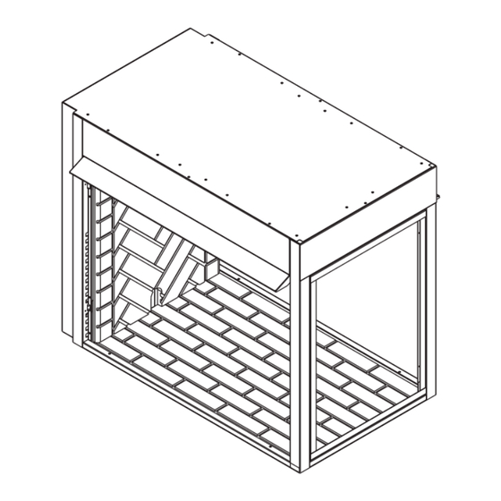
CanopY installation Lo-Rider Designer Vent Free Fireboxes A canopy is furnished with each firebox and MUST be installed for safe operation. Figure 19 1. Align the canopy with the holes in the top frame. 2. Secure canopy with five (5) screws provided. 3 Repeat on other side for See-Through Unit (lSTF36) and Peninsula Unit (lPF36). -
Page 16: Wiring To Junction Box
WirinG to JunCtion box & Glass CleaninG Lo-Rider Designer Vent Free Fireboxes forCeD air kit If you are installing the forced air kit Model BlOTDl on the lSTF36, lPF36, gCRF36 or gClF36 units, see the installation instructions below supplied with kit. electrical connections should only be performed by a qualified, licensed electrician, main power must be off when connecting to main electrical power supply or performing service. - Page 17 replaCement parts Lo-Rider Designer Vent Free Fireboxes stanDarD features item DesCription lrCf/llCf 36” Canopy 71D0500 71D0500 71D0500 20” Canopy 79D0082(1) Screen Panel 79D0001(4) 79D0001(4) 79D0001(3) Screen Rod Side 26D0138(4) 26D0138(4) 26D0138(2) Screen Rod End 43D0116(1) Brick Panel Common 79D0093(1) 79D0093(1) 79D0093(1) Brick Panel Corner 79D0094(1)
- Page 18 use of optional ak-4 outsiDe air kit Lo-Rider Designer Vent Free Fireboxes Combustion air 1. locate combustion air assembly at an exterior location which is not likely to be accidentally blocked in any manner. locate assembly a min. of 12" above the snow line to prevent block- age by snow accumulation.
- Page 19 use of optional ak-4 outsiDe air kit Lo-Rider Designer Vent Free Fireboxes The use of outside air for combustion is optional unless required by building codes. It is only necessary to supply outside combustion air to one side of the fireplace. Use the model AK4 combustion air kit.
- Page 20 use of optional ak-4 outsiDe air kit Lo-Rider Designer Vent Free Fireboxes moDel ak-4 Combustion air assemblY (CONTINUeD) 7. If the duct is the insulated type, push the insulation back from one end of the duct approximately 2". See Figure 29. 8. Slip the exposed end of the duct over the starting collar on the fireplace. 9.
-
Page 21: Warranty
After installation, if any of the components manufactured by MHSC in the appliance are found to be defective in materials or workmanship, MHSC will, at its option, replace or repair the defective components at no charge to the original owner.
Need help?
Do you have a question about the MAJESTIC LFP36 DESIGNER PENINSULA and is the answer not in the manual?
Questions and answers